


Monitor a device Find out if a device is already on or off
Receive alarm messages if a device has been switched on or off
Receive alarm messages if a specified alarm limit has been crossed
Personalize Define your own device commands (aliases)
Disable acknowledgements for device commands
Select the frequency of alarm messages (alarm once/continuously)
Identify the calling party and give permissions for device control
Position Get position information through the Nokia 12 GSM Module when connected to a
GPS device
The Nokia 12 GSM Module processes the control message it receives, and
sends the response as a text message back to the originator. Received and
recognised control messages are not stored in the Nokia 12 GSM Module
memory. If a text message is not recognised as a control message, it is stored
on the SIM card or Nokia 12 GSM Module memory as a normal text message.
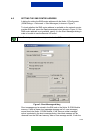
Before you can send control messages to the Nokia 12 GSM Module in order to
control or monitor the device attached to it, you must configure the Nokia 12
GSM Module. Use the Nokia 12 Configurator software, which can be
downloaded at http://www.forum.nokia.com
or
http://www.americas.forum.Nokia.com
. Some configurations are also possible
with control messages; others require that Configurator is used.
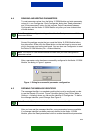
Note: To use Configurator, you need the Nokia 12 GSM Module and a test board.
The Nokia 12 GSM Module is connected to a compatible PC and Configurator with
the test board. A power supply, data cable, antenna adapter, antenna, and SIM
card are also needed. All these items are included in the Nokia 12 GSM Module
test board sales package.
Attach the device to be controlled or monitored with control messages to the
general-purpose inputs and outputs of the M2M system connector of the Nokia
12 GSM Module. There are 11 inputs of which the first three (1-3) are analog
and the rest (4-11) are digital. The Nokia 12 GSM Module has also 9 digital
output pins on the M2M system connector. If the information available from the
device is continuous, select one of the three analog input pins. If the information
is on/off information, use the inputs 4-11. The nine outputs can be used in
digital mode only (set something on/off).
4/49