CC100Master Bridge User’s Guide
2
2
I
I
N
N
S
S
T
T
A
A
L
L
L
L
A
A
T
T
I
I
O
O
N
N
This chapter describes the installation procedure for your bridge.
Packing List
Your package should come with the equipment listed below,
♦ One Main Unit (HCNA to Ethernet Master Bridge) CC100
♦ One DC 5V Power Adaptor
♦ One F-Type Coaxial Cable (RG-59U)
♦ One RJ-45 Ethernet Cable (CAT-5)
Rear Panel
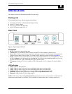
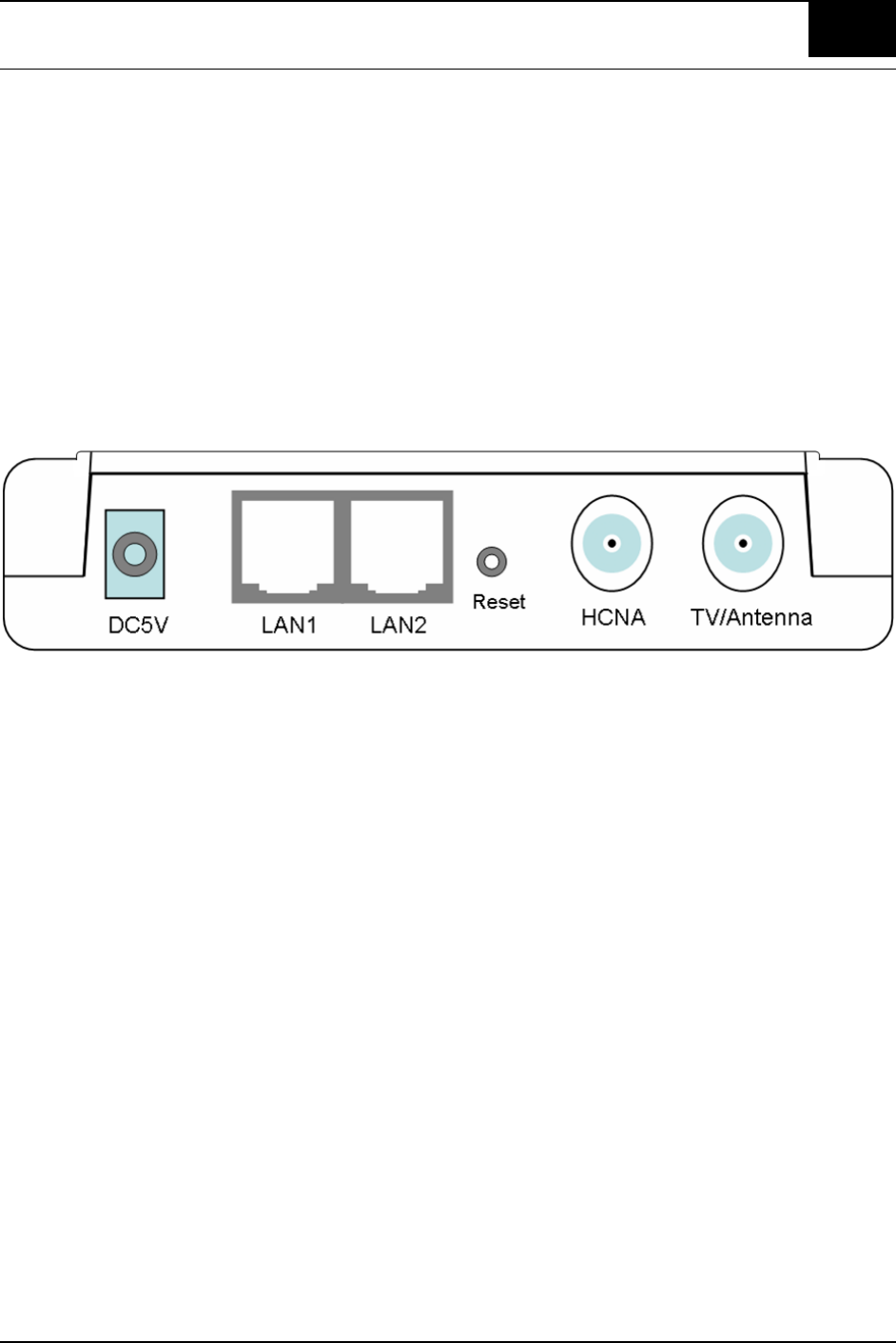
Figure 1: Rear Panel of CC100
Connectors
1. DC5V: Connect to the power adapter plug.
2. LAN1/LAN2: Two fast Ethernet ports to connect Switch/FTTx/xDSL Modem for Internet access.
3. Reset: While CC100 is turned on, press and release this button to reboot CC100. Pressing it for 5 seconds will
restore all settings back to factory default. For example, the IP address will restore to default ‘192.168.1.1’.
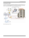
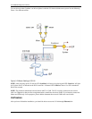
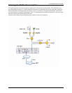
4. HCNA: Attach to existing coaxial cable and use it as the networking backbone in one or more MDUs. CC100 is
the HCNA Master device and controls the other Slave HCNA devices (refer to Endpoint or EP, as CC101) on
the same coax network. Refer “Connecting the Cables” for more details.
5. TV/Antenna: Connect to TV Set. Or connect to VHF/UHF antenna or CATV to bypass TV signal to HCNA
port.
LED Indicators
1. Power: Lights up when power on.
2. LAN1: Lights up when LAN1 port is active and flashing when there is any data traffic.
3. LAN2: Lights up when LAN2 port is active and flashing when there is any data traffic.
4. Link/Act: Lights up when HCNA port is active and flashing when there is any data traffic.
5. SyncMode: Lights up when HCNA port is working in HCNA Synchronous MAC mode.
6. Diagnosis: Lights up when CC100 is diagnosing EP.
NOTE: HCNA always adopts the Synchronous MAC protocol layer in coax system in order to coordinate all the
transmissions and eliminate any collisions. The SyncMode LED should always be on as long as power is on.


