


Appendix A Technical specifications 101
Nortel VPN Router Installation — VPN Router 2750
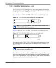
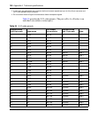
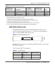
The following notes apply to the single X.21 cable:
1. Wires of pair 4 connect to wires of pair 5, but not to any pins in the DA-15.
2. The term “no conn” means the wire is not connected to a pin in the 15-pin connector.
3. Wires 13B and 14B connect to pin 8 in the 15-pin connector.
4. At each end, the cable shield and connector shell must connect to pin 1 of the connector.
5. Do not interconnect Shield to Signal Ground because these are separate signals.
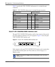
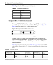
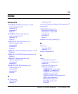
HSSI WAN interface card
The HSSI WAN interface card has a 50-pin SCSI II female connector that
provides the signals needed to interface to a T3 modem or modem eliminator.
Figure 44 shows the HSSI WAN interface card.
Figure 44 HSSI WAN interface card
Included in the accessory box is a cable that maps the T3 signals out to a 50-pin
SCSI II male connector.
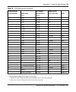
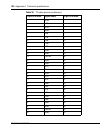
Table 35 provides the T3 cable pinouts.
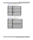
28 M2<-SIGNAL GROUND pair 13B 8 Note 3
1 SHIELD pair 14A 1 Note 4,5
7 SIGNAL GROUND pair 14B 8 Note 3,5
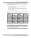
Table 35 T3 cable pinouts
50-pin SCSI male Signal name 50-pin SCSI male
1GND1
2 RCB 2
3CAB3
Table 34 X.21 cable pinouts (continued)
Standard-wired
end 28-pin male Signal name
Pair number
and conductor
Standard-wired
end 15-pin male Notes
CS460003A