


General Installation Passport 4400 Hardware Installation Module
10-3
in its physical location and its logical location Note that even though the High-
Speed Data Module physically resides just above the Ethernet Base Module
(in slot B), logically, its in LIM 1 (because the T1 Voice Module and Digital
Voice Expansion Module must be in LIMs B, C and D).
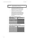
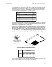
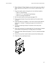
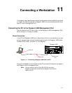
All modules contain a module location switch group, as shown in Figure 10-1 This switch
group informs the software of the module’s logical location within the Passport 4400 unit.
It must be set as shown in the chart on the next page.
In most cases, the module location switch group should match the physical location of the
module. In some instances, the logical location (set by the switch group) will differ from
the physical location. This is true in the case of voice modules in the same unit, such as a
T1 or E1 module. The T1 or E1 module must be set for logical location B, but can reside in
any physical location. Conversely, the High-Speed Data Module must physically reside in
Slot B directly above the Ethernet Base Module, but can logically be placed in LIM 1 or 2.
Figure 10-1. Module Location Switch Group
To set a switch segment to ON, use a ballpoint pen or similar pointed tool and
push the switch down (towards the edge of the module).
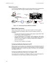
Physical
Slot
Logical
LIM
E DVEM D
D DVEM C
C TVM/EVM B
B HDM 1
Ethernet Base Module
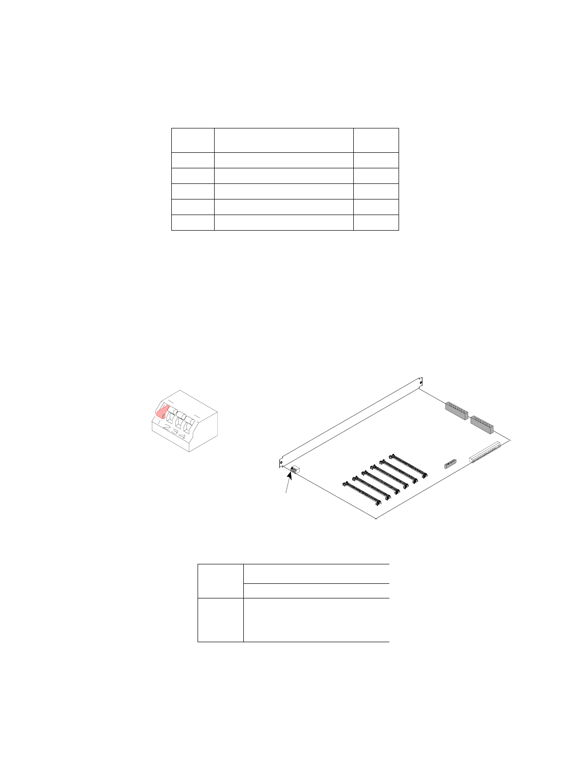
Switch Segment
Location1234
B ON OFF OFF OFF
C OFF ON OFF OFF
D OFF OFF ON OFF
Module Location
Switch Group
O
F
F
O
P
E
N
O
N
Segment 1 in ON position;
segments 2,3,4 in off
position.,
specifying location B.