


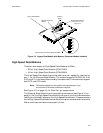
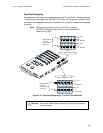
T1, E1, and Digital Voice Modules Passport 4400 Hardware Installation Manual
5-3
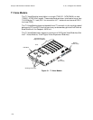
Connectors
and Pin Assignments
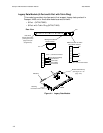
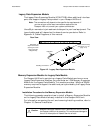
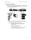
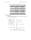
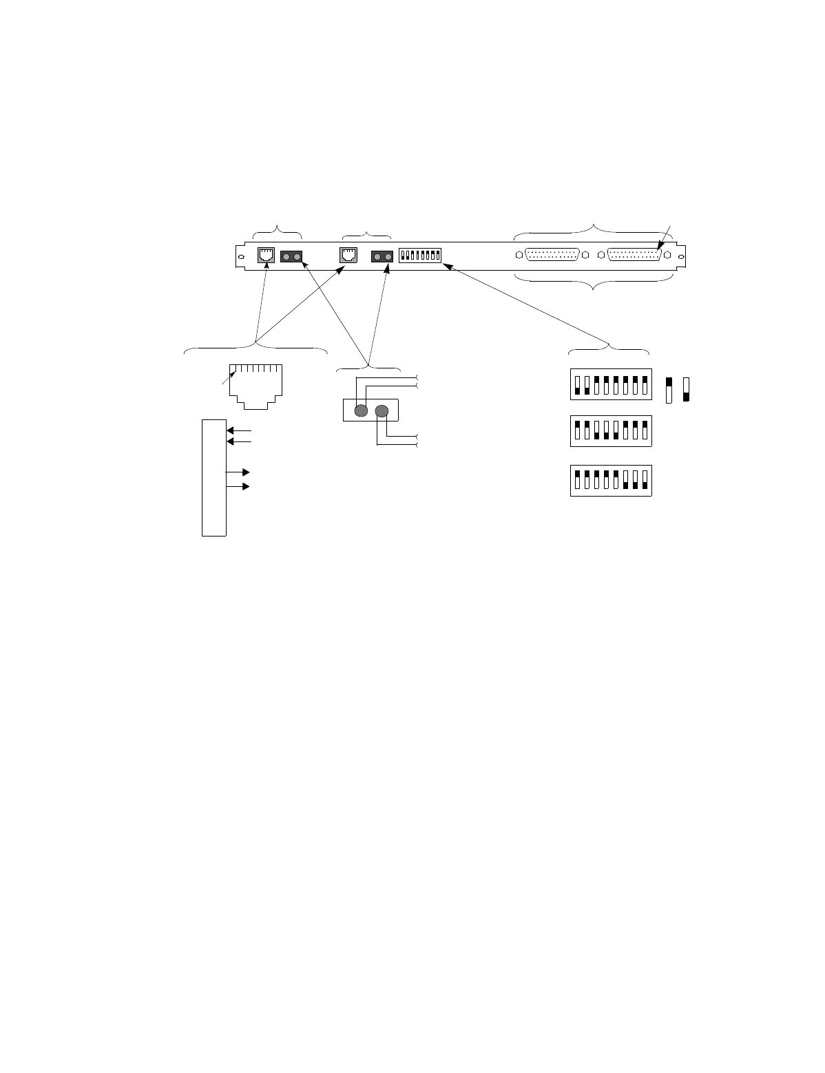
The figure below shows the connectors and pin assignments located on the back-
panel of the T1 Voice Module. All pin assignments and other features are the
same for single and dual port modules.
Figure 5-2. Pin Assignments for T1 Voice Module - Single and Dual Port
Note:
The connections will depend on the specific site
requirements. If you are not sure of the connections required
for the Passport 4400 unit, consult your system administrator
or refer to the following:
• Chapter 11, Connecting a Workstation.
• Appendix A, Cable Diagrams.
• Appendix B, Agency and Telephone Company Requirements.
• Appendix D, T1 Voice Module Cabling Requirements.
DSX-1
(dual-port only)
RJ-48
Transmit Pair
from T1
(Monitor Only)
Transmit Pair
to T1
(Monitor
Only)
Data Ports
1
2
3
4
5
6
7
8
Ring (R)
Tip (T)
Ring 1 (R1)
Tip 1 (T1)
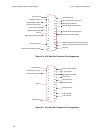
RJ-48
12345678
0 dB
LBO
12345678
-7.5 dB
LBO
12345678
-15 dB
LBO
UP
DOWN
DS-1
See Figure 5-7, Figure 5-8,
and Figure 5-9
Pin 1
Pin 1