(Revised 2010-11-15) Page 18 of 156
defined by the VID or PVID defines a VLAN group with a membership of ports. This membership
determines whether a port is included or excluded as to frame egress from the switch.
The 708M12 Series switch also has the ability to allow overlapping VLANs. Overlapping VLANs give
the user the ability to have one or more ports share two or more VLAN groups. For more information and
examples on how this could be implemented, please see the ‗VLAN Configuration Examples‘ in this
document, and/or our website‘s technical documents. Note that RSTP on overlapping VLANs is not
supported and the system will automatically disable RSTP on all but the lowest VID VLANs that have
overlapping ports.
Rapid Spanning Tree Protocol
The Rapid Spanning Tree Protocol as specified in IEEE 802.1D-2004 is supported. One Spanning Tree per
non-overlapping VLAN is supported. The Rapid Spanning Tree Protocol (RSTP) supersedes the Spanning
Tree Protocol (STP) which was described in IEEE 802.1D-1998. The RSTP is used to configure a simply
connected active network topology from the arbitrarily connected bridges of a bridged network. Bridges
effectively connect just the LANs to which their forwarding ports are attached. Ports that are in a blocking
state do not forward frames. The bridges in the network exchange sufficient information to automatically
derive a spanning tree.
RSTP allows for much quicker learning of network topology changes than the older STP. RSTP supports
new and improved features such as rapid transition to forwarding state. RSTP also sends out new BPDUs
every hello time instead of just relaying them. RSTP interoperates with older STP switches by falling back
to the older STP when the older BPDUs are detected on bridge ports. The user can also manually configure
bridge ports to use the older STP when desired.
SNMP Traps
The 700 Series switch supports up to 5 SNMP Trap Stations to which SNMP Traps will be sent. The switch
supports four standard traps; Link Up, Link Down, Cold Start and Warm Start. SNMP Traps will be sent to
all the stations configured on the switch if a port Link goes up or down, when the switch first powers up and
when the switch is reset.
IGMP Snooping
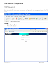
IGMP Snooping is enabled by default, and the switch is Plug and Play for IGMP. IGMP snooping provides
intelligent network support for multicast applications. In particular, unneeded traffic is reduced. IGMP
Snooping is configured via the web console and if enabled, operates dynamically upon each power up.
Also, there can be manual only or manual and dynamic operation. Note that ―static multicast group
address‖ can be used whether IGMP Snooping is enabled or not.
IGMP Snooping will function dynamically without user intervention. If some of the devices in the LAN do
not understand IGMP, then manual settings are provided to accommodate them. The Internet Group
Management Protocol (IGMP) is a protocol that provides a way for a computer to report its multicast group
membership to adjacent ‗routers‘. In this case N-Tron 700 Series switches provide router-like functionality.
Multicasting allows one computer to send content to multiple other computers that have identified
themselves as interested in receiving the originating computer's content. Multicasting can be used to
transmit only to an audience that has joined (and not left) a multicast group membership. IGMP version 2 is
formally described in the Internet Engineering Task Force (IETF) Request for Comments (RFC) 2236.


