3-4 DaqBook Hardware 01-23-02 OMB-DaqBook User’s Manual
Jumpers
Proper installation requires that several jumpers and switches be set correctly for your application. These
jumpers and switches are located inside the DaqBook enclosure and possibly on your DBKs. Jumpers for
the various DaqBook models are configured similarly except for the jumpers’ relative locations. Silk-
screening on the motherboard identifies jumpers and switches. Note: Even if using the default settings,
you should verify actual jumper positions.
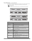
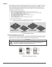
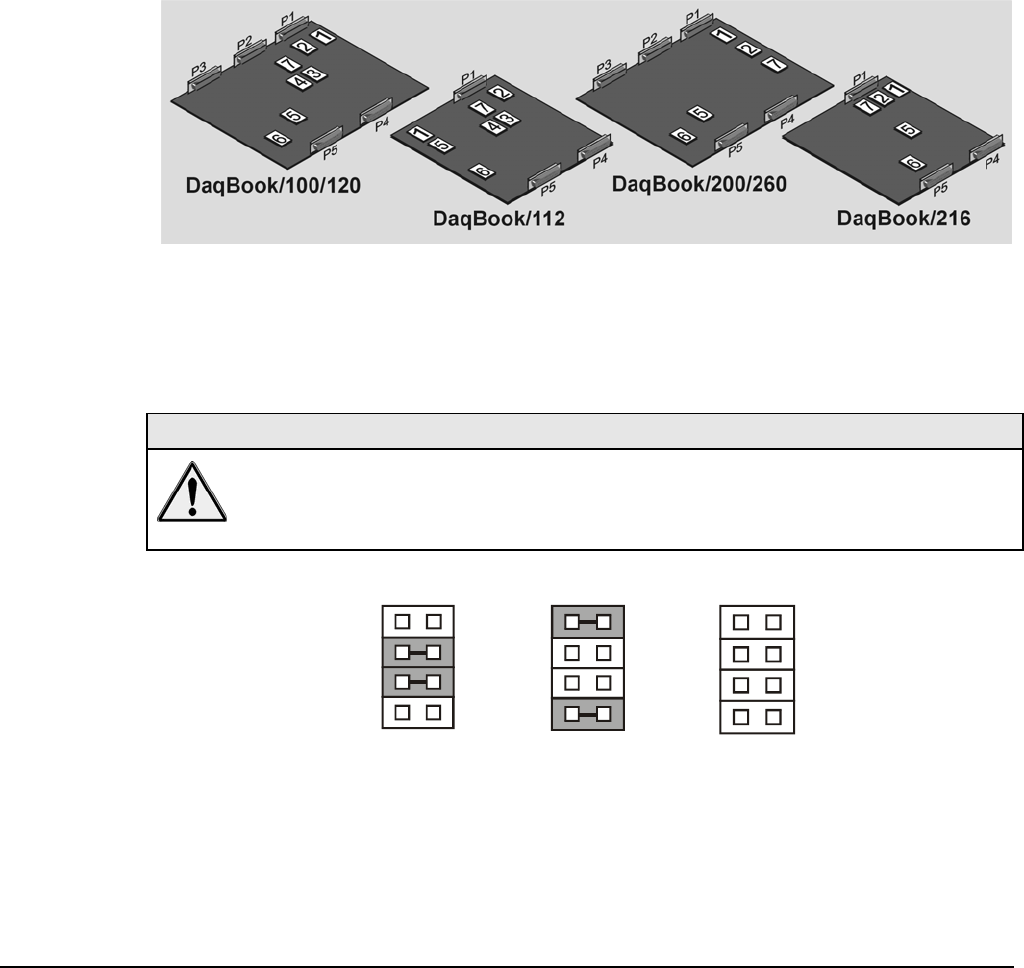
The DaqBook configuration jumpers include:
• JP1 - External Analog Expansion Power; default is Analog Option Card Use
• JP2 - DAC Voltage Reference; default is DAC0 and DAC1 internal reference with SSH
• JP3 - Unipolar/Bipolar; default is bipolar (Note 1)
• JP4 - Differential/Single Ended; default is single ended (Note 1)
• JP5 - Time Base; default is 1 MHz
• JP6 - Watchdog Timer; default is Watch Dog timer disabled
• JP7 - Reserved for factory use.
Note 1: DaqBook/200, DaqBook /216, and DaqBook /260 do not have JP3 and JP4 jumpers.
For these products the related settings are made via software.
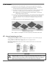
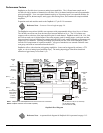
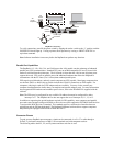
Location of DaqBook Jumpers
External Analog Expansion Power (JP1)
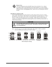
This 4×2 header (JP1) has 3 possible settings. If analog option cards (DBKs) are used, the JP1 pins are set
to provide +15 and -15 VDC to the cards. If such cards are not used, the counter/timer CTR0 is available,
and JP1 must be set accordingly. The default setting is for use of analog option cards.
CAUTION
If using a DBK32A Auxiliary Power Supply or a DBK33 Triple-Output Power Supply
Card, the JP1 shunt jumpers must be entirely removed. Placing the jumpers on
-OCTOUT and -OCLKIN will damage the 8254 timer chip.
JP1
-15 V
-OCTOUT
-OCLKIN
+15 V
Analog Option
Card Use
JP1
-15V
-OCTOUT
-OCLKIN
+15 V
Counter/Timer Use
(16-bit Mode Only)
JP1
-15 V
-OCTOUT
-OCLKIN
+15 V
DBK32A or DBK33
Option Card Use
JP1 External Analog Expansion Settings


