pg. 2, OMB-DBK Basics 02-19-02 Daq Systems
Reference Notes: During software installation, Adobe
®
PDF versions of user manuals will
automatically install onto your hard drive as a part of product support. The default location
is in the Programs directory, which can be accessed from the Windows Desktop. Refer to
the PDF documentation, especially the DBK Option Cards and Modules User’s Manual
(p/n OMB-457-0905) for details regarding both hardware and software in relevant to DBKs.
A copy of the Adobe Acrobat Reader
®
is included on your CD. The Acrobat Reader
provides a means of reading and printing the PDF documents. Note that hardcopy versions
of the manuals can be ordered from the factory.
How Do DBKs Connect to the Data Acquisition Device?
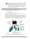
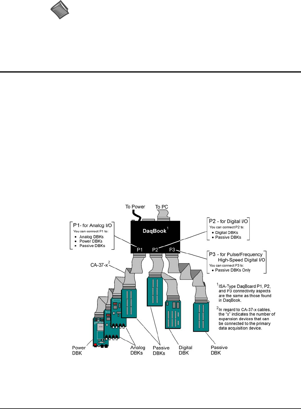
Each DBK connects to the primary data acquisition device; e.g., a DaqBook, DaqBoard, or LogBook,
through one of three 37-pin ports, which are designated as follows:
• P1 – Analog I/O
• P2 – Digital I/O
• P3 – Pulse/Frequency/High-Speed Digital I/O
Depending on the primary data acquisition device, connectivity issues differ slightly. This will be made
clear by the figures and accompanying text that follow.
For DaqBooks, ISA-Type DaqBoards, and LogBooks, DBK connections are not made directly to the port,
but through a CA-37-x ribbon cable, where “x” indicates the number of expansion devices that can be
connected. For example, in addition to providing a DB37 connector to interface with the primary data
acquisition device, a CA-37-3 cable includes three additional DB37 connectors. These provide a means of
adding three DBKs to one port. Use of a CA-37-16 cable will allow up to 16 DBKs to be added. The
CA-37-x cable system is excellent for DaqBooks, LogBooks, and ISA-type DaqBoards.
Connecting DBKs to a DaqBook
The above figure applies to LogBooks, DaqBooks, and ISA-type DaqBoards. As will be seen elsewhere in
the documentation, some models do not include all three connectors (P1, P2, and P3).


