Daq Systems 02-19-02 OMB-DBK Basics, pg. 1
DBK Basics
Introduction…… 1
How Do DBKs Connect to the Data Acquisition Device? …… 2
DBK Identification Tables ….. 3
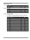
Analog Output DBKs …… 3
Digital I/O Control DBKs …… 3
Analog Signal Conditioning DBKs …… 3
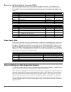
Expansion and Terminal Panel Connection DBKs …… 4
Power Supply DBKs …… 4
Tips on Setting up a Data Acquisition System …… 4
Power Supplies and Power Connectors ……6
An Introduction to Power-Related DBKs ….. 7
Calculating Your System’s Power Needs …… 9
Additional Reading ….. 11
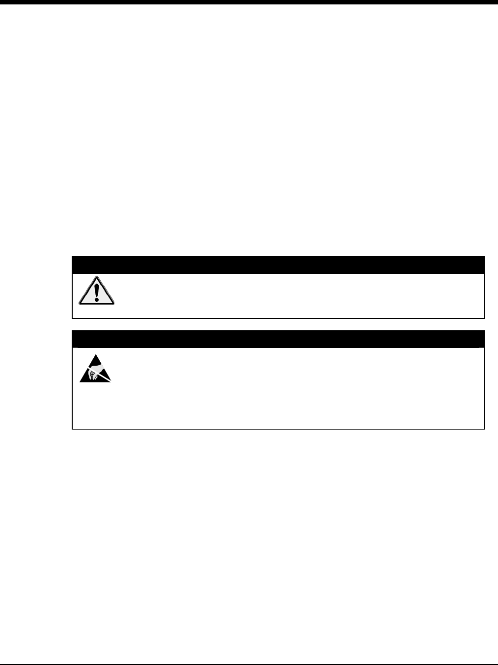
CAUTION
Turn off power to all devices connected to the system before connecting cables or
setting configuration jumpers and switches. Electrical shock or damage to
equipment can result even under low-voltage conditions.
CAUTION
The discharge of static electricity can damage some electronic components.
Semiconductor devices are especially susceptible to ESD damage. You should
always handle components carefully, and you should never touch connector pins or
circuit components unless you are following ESD guidelines in an appropriate ESD
controlled area. Such guidelines include the use of properly grounded mats and
wrist straps, ESD bags and cartons, and related procedures.
Introduction
The term “DBK” typically refers to a card or module that is used to expand or enhance a primary data
acquisition device, such as a DaqBook, DaqBoard, or LogBook. As will be seen in the upcoming DBK
identification tables, DBKs provide a wide variety of data acquisition functions. Depending on the DBKs
used, one or more of the following can be realized:
• signal conditioning
• analog output
• digital I/O
• channel expansion
• supplying powering to another acquisition device
• providing an interface for different connectivity.


