3-14 DaqBook Hardware 01-23-02 OMB-DaqBook User’s Manual
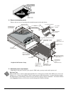
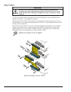
4 – Remove termination panels
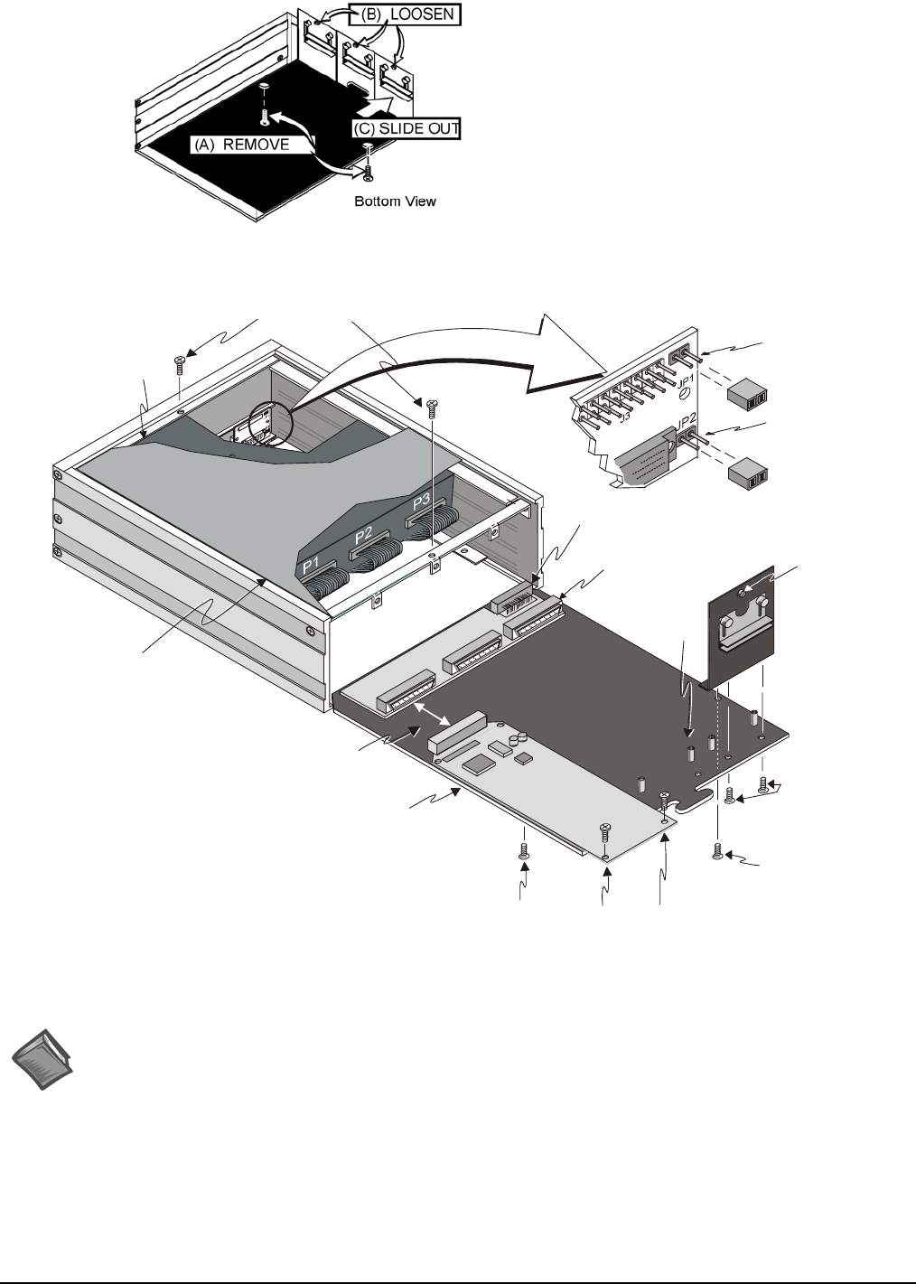
Remove the two screws mounting each termination panel to the card drawer.
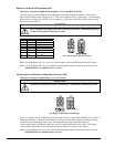
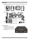
P1 Interconnect Board
DaqBook/200 sits
on a shelf above
the card drawer
Card Drawer to Chassis Connector
Termination Panel
(1 of 3)
JP1 Jumper
Step 6B
JP2 Jumper
Step 6A
Standoff
(2 per card)
Card Drawer
DBK Card to
Interconnect Board
Steps 7A and 10A
Top Cover
()cut-away view
Internal DB37 connects
to DBK cards. (1 of 3)
DaqBook/260 Hardware Setup
Thumbscrew
(1 of 3)
Steps 3B and 13C
Termination Panel to
Card Drawer Screws
Steps 4 and 12
DBK Card to
Card Drawer Screws
Steps 7B and 10B
Card Drawer to
Chassis Screw
(1 of 2)
Steps 3A and 13D
Card Drawer to
Chassis Screw
(1 of 2)
Steps 3A and 13D
Top Cover Screws
Steps 2 and 15
5 – Determine power requirements
Depending on the power needs of your system’s DBK cards, you may need to add a power card.
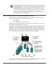
Reference Note:
Both the DBK Basics section of this manual and the Power Management section of the DBK Option Cards and
Modules User’s Manual (p/n OMB-457-0905) contain power-related information. As a part of product support,
the DBK manual is automatically loaded onto your hard drive during software installation. The default location
is the Programs directory, which can be accessed through the Windows Desktop.
DaqBook/260 Hardware Setup


