


2 Instructions
2-262
CP1E CPU Unit Instructions Reference Manual(W483)
Note 1 When the unit is designated as 1, the range is from 1 to 8,191 times the period. When the unit is designated as 9, the
range is from 0.1 to 819.1 s. When 9 is designated, set the integral and derivative times to within a range of 1 to 8,191
times the sampling period.
2 Setting the 2-PID parameter (α) to 000 yields 0.65, the normal value.
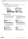
3 When the manipulated variable output limit control is enabled (i.e., set to “1”), set the values as follows:
0000 ≤ MV output lower limit ≤ MV output upper limit ≤ Max. value of output range
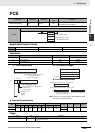
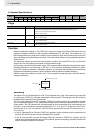
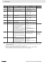
Bit 00 of C+5 PID forward/reverse
designation
Determines the direction of the proportional
action.
0: Reverse action
1: Forward action
Not allowed
Bit 12 of C+6 Manipulated variable
output limit control
Determines whether or not limit control will apply
to the manipulated variable output.
0: Disabled (no limit control)
1: Enabled (limit control)
Bits 08 to 11
of C+6
Input range The number of input data bits. 0: 8 bits 5: 13 bits
1: 9 bits 6: 14 bits
2: 10 bits 7: 15 bits
3: 11 bits 8: 16 bits
4: 12 bits
Bits 04 to 07
of C+6
Integral and deriva-
tive unit
Determines the unit for expressing the integral
and derivative constants.
1: Sampling period multiple
9: Time (unit: 100 ms)
Bits 00 to 03
of C+6
Output range The number of output data bits. (The number of
output bits is automatically the same as the num-
ber of input bits.)
0: 8 bits 5: 13 bits
1: 9 bits 6: 14 bits
2: 10 bits 7: 15 bits
3: 11 bits 8: 16 bits
4: 12 bits
C+7 Manipulated variable
output lower limit
The lower limit for when the manipulated variable
output limit is enabled.
0000 to FFFF (binary)
(See note 3.)
C+8 Manipulated variable
output upper limit
The upper limit for when the manipulated variable
output limit is enabled.
0000 to FFFF (binary)
(See note 3.)
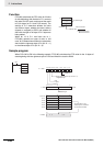
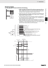
Bit 15 of C+9 AT Command Bit This control bit starts autotuning.
• Set the AT Command Bit to 1 to perform auto-
tuning. (Autotuning can be started while
PIDAT(191) is being executed.)
• This bit is turned OFF automatically when auto-
tuning is completed.
Autotuning will be interrupted if the AT Command
Bit is turned OFF manually. In this case, the PID
constants will be enabled if they were already cal-
culated when autotuning was interrupted.
As a Control Bit:
• 0
→ 1:
Executes autotuning.
• 1
→ 0:
Interrupts autotuning.
(PID(191) turns the bit OFF automatically
when autotuning is completed.
As a Flag:
0: Autotuning is not being executed.
1: Autotuning is being executed.
Allowed
Bits 00 to 11
of C+9
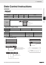
AT Calculation Gain Set this parameter to adjust the contribution of the
PID calculation results to the stored values.
Normally, leave this parameter set to its default
(0000).
• Increase the value when emphasizing stability.
• Decrease the value when emphasizing respon-
siveness.
0000 hex: 1.00 (Default)
0001 to 03E8 hex (1 to 1000);
(0.01 to 10.00, in units of 0.01)
Allowed
(These parameters
are read when
autotuning starts.)
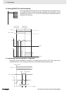
C+10 Limit-cycle Hysteresis Sets the hysteresis when the limit cycle is gener-
ated. The default setting for reverse operation
turns ON the MV with a hysteresis of SV−20%.
Increase this setting if a proper limit cycle cannot
be generated because the PV is unstable. How-
ever, the AT accuracy will decline if the Limit-cycle
Hysteresis is higher than necessary.
0000 hex: 0.20% (Default)
0001 to 03E8 hex:
0.01 to 10.00% in units of 0.01%
FFFF hex: 0.00%
NoteThe percentage is with respect to the
input range.
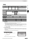
Control data Item Contents Setting range
Change with ON
input condition