


2 Instructions
2-358
CP1E CPU Unit Instructions Reference Manual(W483)
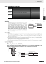
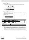
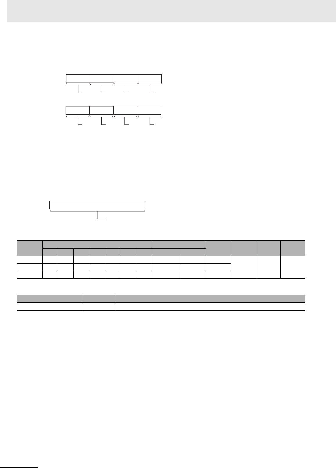
D: First Result Word
Specifies the leading word address where the external digital switch’s set values will be stored.
C1: Number of Digits
Specifies the number of digits that will be read from the external digital switch. Set C1 to 0000 hex to
read 4 digits or 0001 hex to read 8 digits.
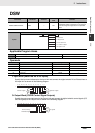
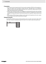
C2: System Word
Specifies a work word used by the instruction. This word cannot be used in any other application.
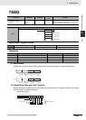
Operand Specifications
Flags
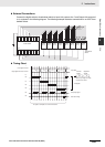
Function
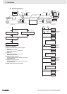
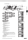
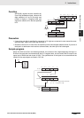
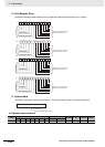
DSW(210) outputs control signals to bits 00 to 04 of O, reads the specified number of digits (either 4-
digit or 8-digit, specified in C1) of digital switch data line data from I, and stores the result in D and D+1.
(If 4 digits are read, the result is stored in D. If 8 digits are read, the result is stored in D and D+1.)
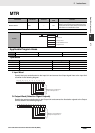
DSW(210) reads the 4-digit or 8-digit switch data once every 16 cycles, and then starts over and contin-
ues reading the data. The One Round Flag (bit 05 of O) is turned ON once every 16 CPU Unit cycles.
Area
Word addresses Indirect DM addresses
Constants CF Pulse bits TR bits
CIO WR HR AR T C DM @DM *DM
I, O, D OKOKOKOKOKOKOK OK OK ---
--- --- ---C1 --- --- --- --- --- --- --- ---
---
OK
C2 OK OK OK OK OK OK OK OK ---
Name Label Operation
Error Flag P_ER OFF
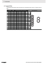
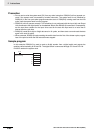
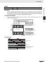
D
815 12 11 0347
D+1
815 12 11 0347
Digit 1
Digit 2
Digit 3
Digit 4
Digit 5
Digit 6
Digit 7
Digit 8
Note: Only when C1 = 0001 hex to read 8 digits.
(See note.)
C2
15 0
System word
(Cannot be accessed b
y the user.)