


2 Instructions
2-376
CP1E CPU Unit Instructions Reference Manual(W483)
Function
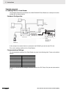
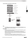
• RXD(235) reads data that has been received in no-protocol mode at the CPU Unit’s built-in RS-232C
port or the Serial Option Board port (the port is specified with bits 8 to 11 of C) and stores N bytes of
data in words D to D+(N÷2)-1. If N bytes of data has not been received at the port, then only the data
that has been received will be stored.
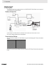
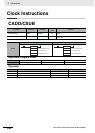
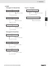
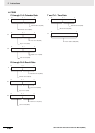
• The following receive message frame format can be set in the PLC Setup.
1) Start code: None or 00 to FF hex
2) End code: None, CR+LF, or 00 to FF hex. If no end code is specified, the number of bytes to
received is set from 00 to FF hex (1 to 256 decimal; 00 specifies 256 bytes).
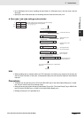
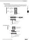
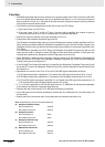
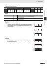
• Data will be stored in memory in the order specified in C0 to C3.
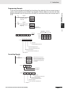
• Cases where the reception completion flag turns ON
The Reception Completed Flag (note (a)) will turn ON when the number of bytes specified in the PLC
Setup has been received. When the Reception Completed Flag turns ON, the number of bytes in the
Reception Counter (note (b)) will have the same value as the number of receive bytes specified in the
PLC Setup.
If an end code is specified in the PLC Setup, the Reception Completed Flag (note (a)) will turn ON
when the end code is received or when 256 bytes of data have been received. If more bytes are
received than specified, the Reception Overflow Flag (note (c)) will turn ON.
• When RXD(235) is executed, data is stored in memory starting at D, the Reception Completed Flag
(note (a)) will turn OFF (even if the Reception Overflow Flag (note (c)) is ON), and the Reception
Counter (note (b)) will be cleared to 0.
• If the RS-232C Port Restart Bit (note (d)) is turned ON, the Reception Completed Flag (note (a)) will
be turned OFF (even if the Reception Overflow Flag is ON), and the Reception Counter (note (b)) will
be cleared to 0.
• Specification of monitor in bits C4 to C7 for the CS and DR signals takes effect as follows:
1) If CS signal monitoring is specified in C, the status of the CS signal will be stored in bit 15 of D.
2) If DR signal monitoring is specified in C, the status of the DR signal will be stored in bit 15 of D.
3) If CS and DR signal monitoring is specified in C, the status of the CS signal will be stored in bit 15
of D and the status of the DR signal will be stored in bit 14 of D.
• If 1, 2, or 3 hex is specified for CS and DR signal control in C, RXD(235) will be executed regardless
of the status of the Receive Completed Flag (note (a)).
• Receive data will not be stored if CS or DR signal monitoring is specified.
• Up to 259 bytes can be received, including the receive data (N = 256 bytes max.), the start code, and
the end code.
• Specify the size of the receive data, not including the start code and end code, in N.
Note Related Auxiliary Area and CIO Area Addresses
(a) Reception Completed Flags
Built-in RS232C port A392.06
Serial Option Board port: A392.14
(b) Reception Counters
Built-in RS232C port A393
Serial Option Board port: A394
(c) Reception Overflow Flags
Built-in RS232C port A392.07
Serial Option Board port: A392.15
(d) RS-232C Port Restart Bit
Built-in RS232C port A526.00
Serial Option Board port: A526.01