


2-367
2 Instructions
CP1E CPU Unit Instructions Reference Manual(W483)
Basic I/O Unit Instructions
2
7SEG
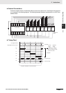
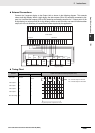
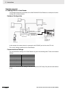
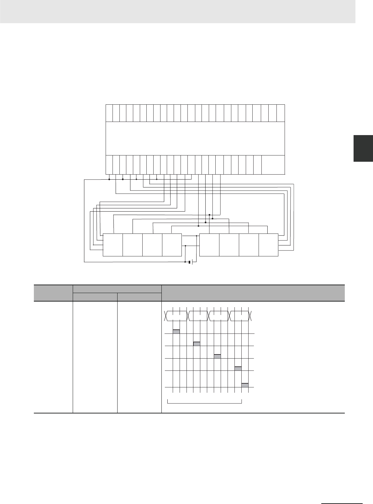
External Connections
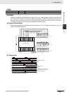
Connect the 7-segment display to the Output Unit as shown in the following diagram. This example
shows an 8-digit display. With a 4-digit display, the data outputs (D0 to D3) would be connected to out-
puts 0 to 3 and the latch outputs (LE0 to LE3) would be connected to outputs 4 to 7. Output point 12 (for
8-digit display) or output point 8 (for 4-digit display) will be turned ON when one round of data has been
output, but it is not necessary to connect them unless required by the application.
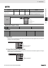
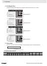
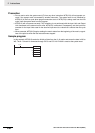
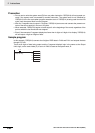
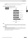
Timing Chart
Function
Bit(s) in O
Output status (Data and latch logic depends on C)
(4 digits, 1 block) (4 digits, 2 blocks)
Data output 00 to 03
00 to 03
04 to 07
Latch output 0 04 08
Latch output 1 05 09
Latch output 2 06 10
Latch output 3 07 11
One Round Flag 08 12
COM
00
01
02
03
04
05
06
07
08
09
10
11
00
01
02
03
04
05
06
07
08
09
10
11
IN@ CH IN@ CH
CP1W-40EDT
OUT@ CH OUT@ CH
COM
00
COM
01
COM
02
03
COM
04
05
06
07
COM
00
01
02
03
COM
04
05
06
07
LE3 LE2 LE1 LE0
D0
D1
D2
D3
VDD
(+)
VSS
(0)
LE3 LE2 LE1 LE0
VDD
(+)
VSS
(0)
D0
D1
D2
D3
7-se
g
ment display
Leftmost 4 digits
Rightmost 4 digits
10
0
10
1
10
2
10
3
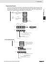
1 2 3 4 5 6 7 8 9 10 11 12 1
12 cycles required to complete one round
Note 0 to 3: Data output for word S
4 to 7: Data output for word S+1