71
Wiring Section 3-3
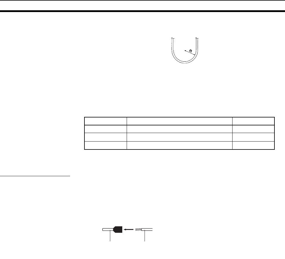
10. When bending a communications cable, allow 60 mm or more for the bend-
ing radius (R).
11. Do not place any object on the communications cable.
12. Supply power only after checking the wiring thoroughly.
13. Connect the terminal block only after checking it thoroughly.
14. Marks are provided on the terminal block for the signal lines. Connect the
signal lines according to the marks. The marks correspond to signal lines
as listed below.
3-3-2 Repeater Units
Power Supply Wiring
Repeater Units must be supplied with DC power. The procedure for wiring the
power supply is the same for all Repeater Units (CS1W-RPT01/02/03).
Use the following procedure to wire the power supply to Repeater Units.
1,2,3... 1. Attach the following crimp terminal to each of the two power lines.
Crimp terminal: AI Series manufactured by Phoenix Contact
The following specialized tool is available for this purpose:
ZA3 manufactured by Phoenix Contact
2. Insert the crimp terminals on the positive and negative power lines into the
orange power connectors located near the bottom of the front panel of the
Repeater Unit. Insert the positive line in the top and the negative line in the
bottom.
3. Use a small, flat-blade screwdriver to fasten the crimp terminals in place.
Note 1. Supply power to the Repeater Unit using a power supply installed specifi-
cally for the Repeater Unit. Do not supply power to the Repeater Unit from
an I/O power supply, motor power supply, or control power supply.
2. To prevent the power supply from being affected by noise, wire and install
the power supply away from power lines and high-voltage lines.
3. Attach special-purpose crimp terminals to the power cables.
4. Do not connect the positive and negative lines to the wrong connectors.
5. The power cable screws should be fastened to a tightening torque of
0.2 N·m.
6. Do not pull on the power cable.
7. Do not bend the power cable past its natural bending radius.
Mark Signal name Line color
g
BDH (communications data high) Black
@
BDL (communications data low) White
None SHLD (shield) ---
Crimp terminal Cable
Insert the cable and then crimp the terminal.


