


SVC Tunneling Basic Configuration and Setup
8-14 Centillion 1200N ATM Switch User Manual
NTP 297-8103-903
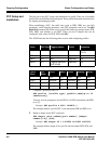
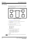
SVC Tunneling
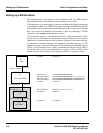
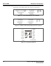
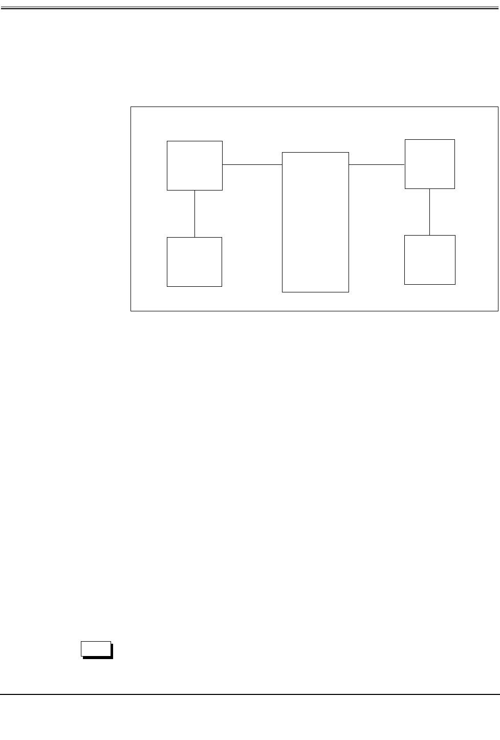
This section describes how to interconnect two ATM Switches (1 & 2) configured
for LAN Emulation with an LE client attached to each, over a PVC connection
using a SVC tunneling technique.
Figure 8-1: SVC Tunneling
1.
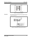
Refer to Figure 8-1 and make cable connections.
2.
Set up both LE clients and Switch 3 configurations except for switch
interconnections.
3.
On Switch 1 and 2, set interface 00 to a NNI port.
4.
On Switch 2, set to User Side.
5.
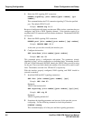
On Switch 1 and 2, execute the following commands:
SET tunnel 00 1
SET signal 00 1
SET ILMI 00 1
6.
On Switch 1 execute the following command:
route add NSAP 47007922 00 1
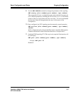
7.
On Switch 2 execute the following command:
route add NSAP 47007911 00 1
8.
SAVE
All signaling, ILMI and SVCs will use VPI and will pass unobstructed through
Switch 3.
470079-11111111111111111111
470079-22222222222222222222
ATM
Switch
(1)
ATM
Switch
(2)
PC
LES/LEC
PC
LES/MAT
ATM Switch
(3)
(PVC)
VPI = 1
Clock:
00.n
000
001
00.u
133.205.8.39
133.205.8.54
NOTE