Ongoing Configuration Basic Configuration and Setup
8-6 Centillion 1200N ATM Switch User Manual
NTP 297-8103-903
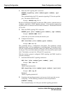
4.
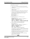
Delete the SVC signaling PVC connection.
DELETE signaling [slot number][port number] [vpi
number]
This command deletes the PVC connection signaling VCI for the specified
port. The default VPI/VCI is 0/5.
Example:
DELETE sig 23 0
Because of intelligent traffic being sent between ATM switches, sometimes the port
configures itself with a PNNI signaling channel. If the interface needs to be
modified, this PVC connection will also need to be deleted. The default PNNI VPI/
VCI is 0/18.
5.
Delete the PNNI signaling PVC connection.
DELETE pnni [slot number][port number] [vpi number]
Example:
DELETE PNNI 23 0
At this time you are able to modify the interface port.
6.
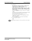
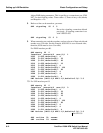
Configure the interface.
SET interface [slot number][port number]
Example:
SET int 23
This command opens a configuration sub-routine. The parameters already
identified in Step 1 will be prompted on an individual basis. Remember that the
VPI and VCI bit field entries DO NOT identify the VPI/VCI that you will be using
for the port. These two fields identify the number of bits that will be used for each
field. The defaults are 6 and 8 for VPI and VCI, respectively.
With the interface properly configured, ILMI signaling and PNNI should be
restored (as needed).
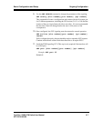
7.
Install the ILMI and SVC signaling connections.
SET ilmi [slot number][port number] [vpi]
Example:
SET ilmi 23
Default=0
VPI/VCI ilmi default=0/16
SET signaling [slot number][port number] [vpi][vci]
Example:
SET sig 23
Default=0
VPI/VCI signaling default=0/5
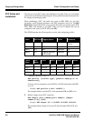
8.
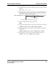
Sometimes the signaling parameters are incorrect for the port that you are
configuring. Use the following command to check the parameters:
DISPLAY atmsig
This command displays all of the ports and their signaling parameters.


