


RS232C Port Wiring
FP2−CCU
4 − 7
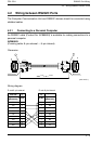
4.2 Wiring between RS232C Ports
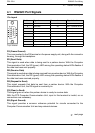
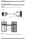
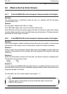
4.2.3 Connections with RS232C Devices
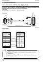
Connections with an RS232C device that has a D −sub 9−pin connector should be made
as follows.
Pin No.
1
2
3
4
5
6
7
8
9
FG
SD
RD
RS
CS
DR
SG
CD
ER
Computer Communication
Unit side
FG
SD
RD
RS
(CS)
SG
(CD)
ER
Pin No.
1
2
3
4
5
6
7
8
9
RS232C side (9−pin)
Mnemonic
Mnemonic
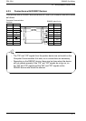
− The “CS” and “CD” signals from the partner device are set invalid on the
Computer Communication Unit side, so no connections are necessary.
− Depending on the RS232C device, there may be times when the device
will not operate properly if the “CS” and “CD” signals do not go on, so
the “RS” and “CS” signals and the “ER” and “CD” signals on the
RS232C device side should be shorted.
Tip