


RS232C Port WiringFP2−CCU
4 − 3
4.1 RS232C Port Signals
4.1 RS232C Port Signals
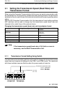
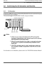
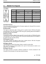
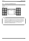
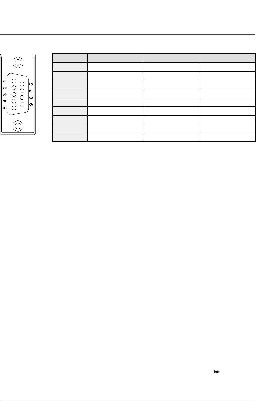
Pin layout
Pin No. Signal Mnemonic Signal direction
1 Frame Ground FG —
2 Send Data SD
Unit → External device
3 Receive Data RD
Unit ← External device
4 Request to Send RS
Unit → External device
5 Clear to Send CS
Unit ← External device
6 (Not used) — —
7 Signal Ground SG —
8 Receive Carrier Detect CD
Unit ← External device
9 Equipment Ready ER
Unit → External device
FG (Frame Ground)
This is connected to the FG terminal on the power supply unit, along with the connector
housing, through the backplane.
SD (Send Data)
This signal is used when data is being sent to a partner device. With the Computer
Communication Unit, the SD (green) LED among the operating status LEDs flashes if
the data has been sent properly.
RD (Receive Data)
This signal isused when data isbeing received from apartner device. Withthe Computer
Communication Unit, the RD (green) LED among the operating status LEDs flashes if
the data has been received properly.
RS (Request to Send)
This signal requests that data be sent from a partner device. With the Computer
Communication Unit, the RS signal is constantly on.
CS (Clear to Send)
This signal goes on when the partner device is ready to receive data.
With the FP2 Computer Communication Unit, input to this terminal is invalid, so no
connections are necessary.
SG (Signal Ground)
This signal provides a common reference potential for circuits connected to the
Computer Communication Unit and any external devices.
next page
9−pin internal