ENGLISH - 21
Chapter 1 Preparation — About your projector
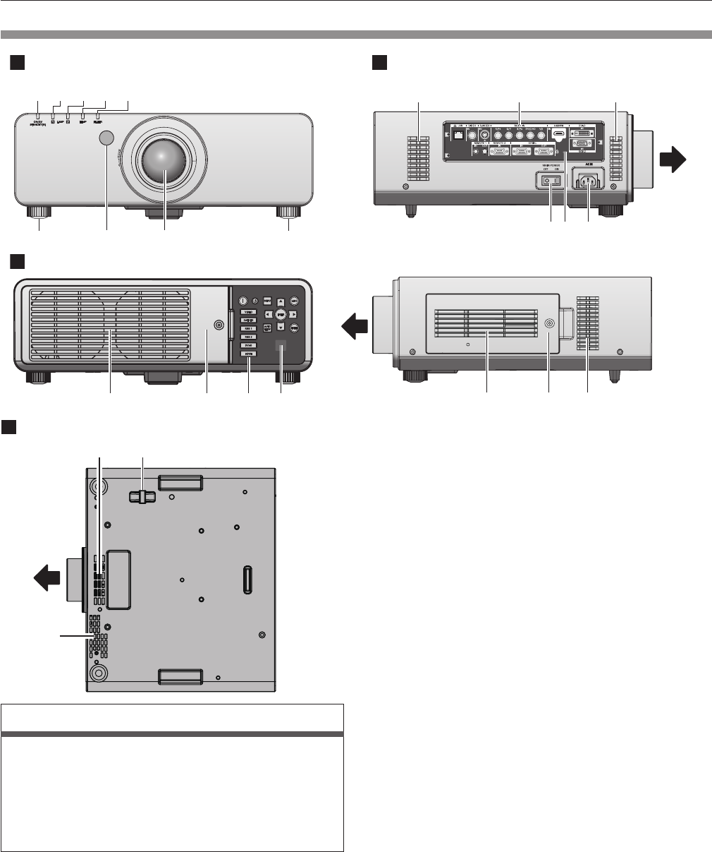
Projector body
12345
6786
9101112
15 16 17
13 14 13
18 1313
Front
Front
Front Side
Rear
1913
13
Front
Bottom
Warning
Keep your hands and other objects away from the air exhaust
port.
rf
Keep your hands and face away.
rf
Do not insert your ngers.
rf
Keep heat-sensitive objects away.
Heated air from the air outlet port can cause bums, injury, or
deformations.
1 Power indicator <ON (G)/STANDBY (R)>
Displays the status of the power.
2 Lamp indicator <LAMP1>
Displays the status of lamp 1.
3 Lamp indicator <LAMP2>
Displays the status of lamp 2.
4 Temperature indicator <TEMP>
Displays the internal temperature status.
5 Filter indicator <FILTER>
Displays the status of the air lter unit.
6 Adjustable feet
Adjusts the projection angle.
7 Remote control signal receiver (front)
8 Projection lens
(for models with attached lenses only)
9 Air exhaust port
10 Lamp unit cover (
x
page 114)
11 Control panel (
x
page 22)
12 Remote control signal receiver (rear)
13 Air intake port
14 Connecting terminals (
x
page 22)
15 <MAIN POWER> switch
Turns on/off the main power.
16 Security slot
This security slot is compatible with the Kensington security
cables.
17 <AC IN> terminal
Connect the supplied power cord.
18 Air lter cover
The air lter unit is inside. (
x
page 112)
19 Burglar hook port
You can attach a commercial burglar prevention cable.


