66 - ENGLISH
Chapter 4 Settings — [ADVANCED MENU] menu
7)
Press qw to switch [ON].
rf
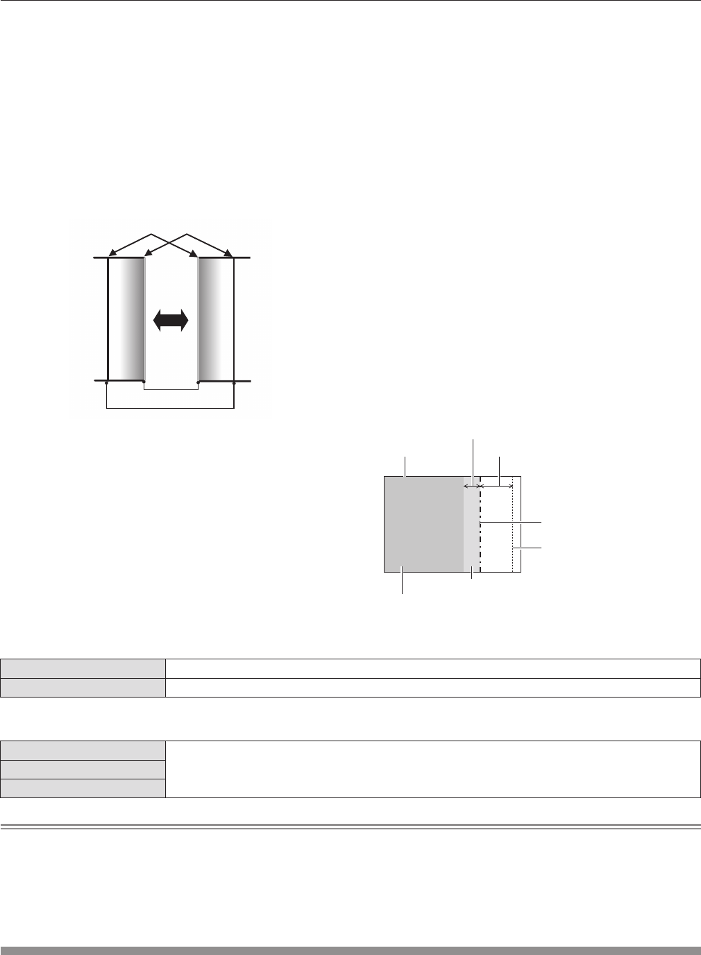
A marker for image position adjustment is displayed.
8)
Press as to select [START] or [WIDTH],
then press qw to adjust starting point and
correction width.
rf
The green line is the starting point of edge blending adjusted
with [START]. The red line is the ending point of edge blending
adjusted with [WIDTH]. The position where the red and green
lines overlap for the sets to join will be the optimal point.
Make sure to set the correction width for the sets to join as the
same value. Optimal joining is not possible with the sets with
different correction widths.
The optimal point is the point at which these lines overlap.
Green line
Red line
9)
Press as to select [GAMMA].
10)
Press qw to switch [GAMMA].
rf
The setting will change among [2.2], [1.8], and [2.0] each time
you press the button.
11)
Press as to select [BRIGHT ADJUST].
12)
Press the <ENTER> button.
rf
The [BRIGHT ADJUST] screen is displayed.
13)
Press as to select [BRIGHT INSIDE].
14)
Press the <ENTER> button.
rf
The [BRIGHT INSIDE] individual adjustment screen is
displayed.
rf
If [INTERLOCKED] is set to [OFF], [RED], [GREEN], and [BLUE]
can be adjusted individually.
15)
Press as to select an item, then press qw to
adjust it.
rf
Once the adjustment is completed, press the <MENU> button to
return to the [BRIGHT ADJUST] screen.
16)
Press as to select [UPPER], [LOWER], [LEFT],
or [RIGHT] from [OUTSIDE AREA].
17)
Press qw to set the region (width) of the
[BRIGHT INSIDE] adjustment.
18)
Press as to select [BRIGHT OUTSIDE].
19)
Press the <ENTER> button.
rf
The [BRIGHT OUTSIDE] individual adjustment screen is
displayed.
rf
If [INTERLOCKED] is set to [OFF], [RED], [GREEN], and [BLUE]
can be adjusted individually.
20)
Press as to select an item, then press qw to
adjust it.
Projection range Edge blending [WIDTH] (Right)
[MARKER] (Red)
Edge blending [START] (Right)
([MARKER] (Green))
[BRIGHT OUTSIDE]
[BRIGHT INSIDE]
rr
[EDGE BLENDING]
[OFF] Sets the edge blending function to off.
[ON] Use the setting value of the internal distortion of the set for the inclination of the edge blending area.
rr
[GAMMA]
[2.2]
The screen becomes darker as the value increases. Set this item according to the condition of the joined
part.
[1.8]
[2.0]
Note
rf
[BRIGHT ADJUST] is a function that makes the increased brightness in black level of the overlapping image area difcult to notice when
[EDGE BLENDING] is used to congure multiple screens. The optimal point of the correction is set by adjusting [BRIGHT INSIDE] so the
black level of the overlapping image area will be the same level as the non-overlapping area. If the bordering part of the part where the
image is overlapping and the non-overlapping part gets brighter after adjusting [BRIGHT INSIDE], adjust the width of the top, bottom, left, or
right. Adjust [BRIGHT OUTSIDE] when the width adjustment makes only the border area darker.
rf
The joining part may look discontinuous depending on the position you are looking from when a screen with high gain or rear screen is used.
[RASTER POSITION]
This will allow the position of the image to move within the display area arbitrarily when the input image is not using the whole display area.
1)
Press as to select [RASTER POSITION].
2)
Press the <ENTER> button.
rf
The [RASTER POSITION] screen is displayed.
3)
Press asqw to adjust the position.


