


22 - ENGLISH
Chapter 1 Preparation — About your projector
rr
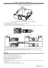
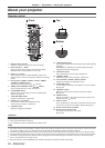
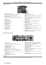
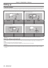
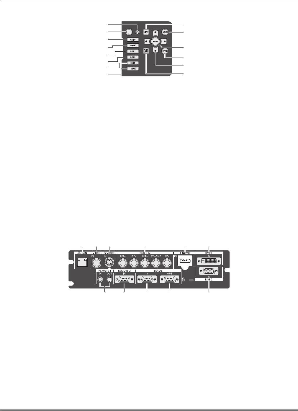
Control panel
9
10
11
12
13
14
1
2
3
4
5
6
7
8
1 Power standby <
v
> button
Sets the projector to the standby mode when the <MAIN
POWER> switch on the projector is set to <ON>.
2 Power on <
b
> button
Starts projection when the <MAIN POWER> switch on the
projector is set to <ON> when the power is switched off (standby
mode).
3 <VIDEO> button
Switches to VIDEO input.
4 <S-VIDEO> button
Switches to S-VIDEO input.
5 <RGB1> button
Switches to RGB1 input.
6 <RGB2> button
Switches to RGB2 input.
7 <DVI-D> button
Switches to DVI-D input.
8 <HDMI> button
Switches to HDMI input.
9 <MENU> button
Displays and erases the main menu.
Returns to the previous screen when a sub-menu is displayed.
(
x
page 51)
If you press the <MENU> button on the control panel for at
least three seconds while the on-screen indication is off, the on-
screen display is turned on.
10 <LENS> button
Adjusts the focus, zoom, and shift (position) of the lens.
11 <ENTER> button
Determines and executes an item in the menu screen.
12 <SHUTTER> button
Use to temporarily turn off the image. (
x
page 47)
13
asqw
selection buttons
Use to select items in the menu screen, change settings, and
adjust levels.
It is also used to enter [SECURITY] passwords.
14 <AUTO SETUP> button
Automatically adjusts the image display position while projecting
the image.
[PROGRESS] is displayed on the screen while the image is
adjusted automatically. (
x
page 48)
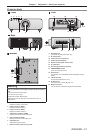
rr
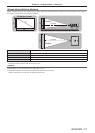
Connecting terminals
1 2 3 4 5 6
7 8 9 10 11
1 <LAN> terminal
This is a terminal to connect to the network.
Used for control and monitoring. Image input through network
connections is not possible.
2 <VIDEO IN> terminal
This is a terminal to input video signals.
3 <S-VIDEO IN> terminal
This is a terminal to input S video signals.
4 <RGB 1 IN> (<R/P
R
>, <G/Y>, <B/P
B
>, <SYNC/HD>, <VD>)
terminal
This is a terminal to input RGB signals or YC
B
C
R
/YP
B
P
R
signals.
5 <HDMI IN> terminal
This is a terminal to input HDMI signals.
6 <DVI-D IN> terminal
This is a terminal to input DVI-D signals.
7 <REMOTE 1 IN> terminal / <REMOTE 1 OUT> terminal
These are the terminals to connect the remote control for serial
control when the system uses multiple projectors.
8 <REMOTE 2 IN> terminal
This is a terminal to remotely control the projector using the
external control circuit.
9 <SERIAL IN> terminal
This is a RS-232C compatible terminal to externally control the
projector by connecting a computer.
10 <SERIAL OUT> terminal
This is a terminal to output the signal connected to the serial
input terminal.
11 <RGB 2 IN> terminal
This is a terminal to input RGB signals or YC
B
C
R
/YP
B
P
R
signals.
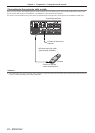
Attention
rf
When a LAN cable is directly connected to the projector, the network connection must be made indoors.