


2-13000-A2-GB41-40 May 1998
Installation
Overview 2-1. . . . . . . . . . . . . . . . . . . . . . . . . . . . . . . . . . . . . . . . . . . . . . . . . . . . . . . . . . . . . . . . . . . . . . . . .
Installation Considerations 2-1. . . . . . . . . . . . . . . . . . . . . . . . . . . . . . . . . . . . . . . . . . . . . . . . . . . . . . . . . . . .
Basic Mode of Operation 2-1. . . . . . . . . . . . . . . . . . . . . . . . . . . . . . . . . . . . . . . . . . . . . . . . . . . . . . . . . . .
Independent Mode of Operation 2-2. . . . . . . . . . . . . . . . . . . . . . . . . . . . . . . . . . . . . . . . . . . . . . . . . . . . .
Redundant Mode of Operation 2-3. . . . . . . . . . . . . . . . . . . . . . . . . . . . . . . . . . . . . . . . . . . . . . . . . . . . . .
Alarm Forwarding to a 6800 Series NMS 2-3. . . . . . . . . . . . . . . . . . . . . . . . . . . . . . . . . . . . . . . . . . . . .
CO Power Unit Installation 2-4. . . . . . . . . . . . . . . . . . . . . . . . . . . . . . . . . . . . . . . . . . . . . . . . . . . . . . . . . . .
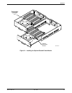
Installing the Optional Second Power Module 2-4. . . . . . . . . . . . . . . . . . . . . . . . . . . . . . . . . . . . . . . . . .
Setting the Option Straps 2-6. . . . . . . . . . . . . . . . . . . . . . . . . . . . . . . . . . . . . . . . . . . . . . . . . . . . . . . . . .
Installing the CO Power Unit 2-9. . . . . . . . . . . . . . . . . . . . . . . . . . . . . . . . . . . . . . . . . . . . . . . . . . . . . . .
Providing Power to a CO Power Unit 2-11. . . . . . . . . . . . . . . . . . . . . . . . . . . . . . . . . . . . . . . . . . . . . . . . .
Installing an SDCP 2-16. . . . . . . . . . . . . . . . . . . . . . . . . . . . . . . . . . . . . . . . . . . . . . . . . . . . . . . . . . . . . . .
Connecting the Alarm Contacts to a CO Alarm System 2-17. . . . . . . . . . . . . . . . . . . . . . . . . . . . . . . . . .
Connecting the Alarm Contacts to a 6800 Series NMS Via a Modular 3611 DSU 2-18. . . . . . . . . . . . . . .
Air Filter and Brackets Installation (Optional) 2-21. . . . . . . . . . . . . . . . . . . . . . . . . . . . . . . . . . . . . . . . . . . .
Overview
The CO Power Unit consists of one power module in a
CO power tray. When installed, the CO Power Unit
provides low voltage dc power to the DCEs in the carrier.
This chapter provides information on how to install the
CO Power Unit into a COMSPHERE 3000 Series Carrier.
Installation Considerations
The CO Power Unit is shipped with one power module
and operates in Basic mode. With an optional second
power module the CO Power Unit can be configured to
operate in either Independent mode or Redundant mode.
If you order a second power module for your CO Power
Unit, you must determine the mode in which you wish to
operate before installing the CO Power Unit.
NOTE
The CO Power Unit installation
procedure must be performed
by a qualified service personnel.
In addition, if you want to forward alarms to a
6800 Series Network Management System (NMS), you
must connect the CO Power Unit to the external leads of a
Modular 3611 DSU. Model 3151 CSUs and Model 3161
DSU/CSUs do not support forwarding of CO Power Unit
alarms to a 6800 Series NMS. To access these external
leads, use an NMS adapter cable to connect the external
leads of a Modular 3611 DSU to the CO Power Unit.
This section describes the three modes of operation and
provides information you need to know in order to send
alarms to a 6800 Series NMS.
Basic Mode of Operation
The CO Power Unit with one power module operates
in Basic mode. In this mode of operation, the single power
module supplies power to the entire carrier.
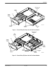
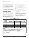
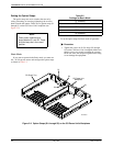
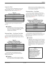
When stacking multiple carriers equipped with CO
Power Units with single power modules, you must install
the power module in each of the CO Power Units in
alternating sequence (that is, left side, right side, left side,
right side, etc.) for proper cooling. For example, if the CO
Power Unit in the bottom carrier has its power module
installed in the left side of the CO power tray, the carrier
2