


3-13000-A2-GB41-40 May 1998
Troubleshooting and Maintenance
Overview 3-1. . . . . . . . . . . . . . . . . . . . . . . . . . . . . . . . . . . . . . . . . . . . . . . . . . . . . . . . . . . . . . . . . . . . . . . . . .
Indicators and Controls 3-1. . . . . . . . . . . . . . . . . . . . . . . . . . . . . . . . . . . . . . . . . . . . . . . . . . . . . . . . . . . . . .
Troubleshooting 3-2. . . . . . . . . . . . . . . . . . . . . . . . . . . . . . . . . . . . . . . . . . . . . . . . . . . . . . . . . . . . . . . . . . . .
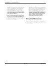
Power Module Replacement Instructions 3-3. . . . . . . . . . . . . . . . . . . . . . . . . . . . . . . . . . . . . . . . . . . . . . . . .
Preventive Maintenance 3-4. . . . . . . . . . . . . . . . . . . . . . . . . . . . . . . . . . . . . . . . . . . . . . . . . . . . . . . . . . . . . .
Overview
This chapter describes the status indicators on the
power module’s faceplate, provides troubleshooting
guidelines and replacement instructions for the power
module, and a preventive maintenance schedule for the
optional air filter.
Indicators and Controls
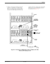
The CO Power Unit detects power module and/or fan
failures by monitoring the power output levels and the
fan’s low-speed sensor for proper operation of the power
module. When a failure occurs, an alarm indication light
appears on the faceplate of the affected power module.
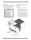
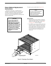
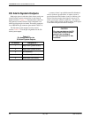
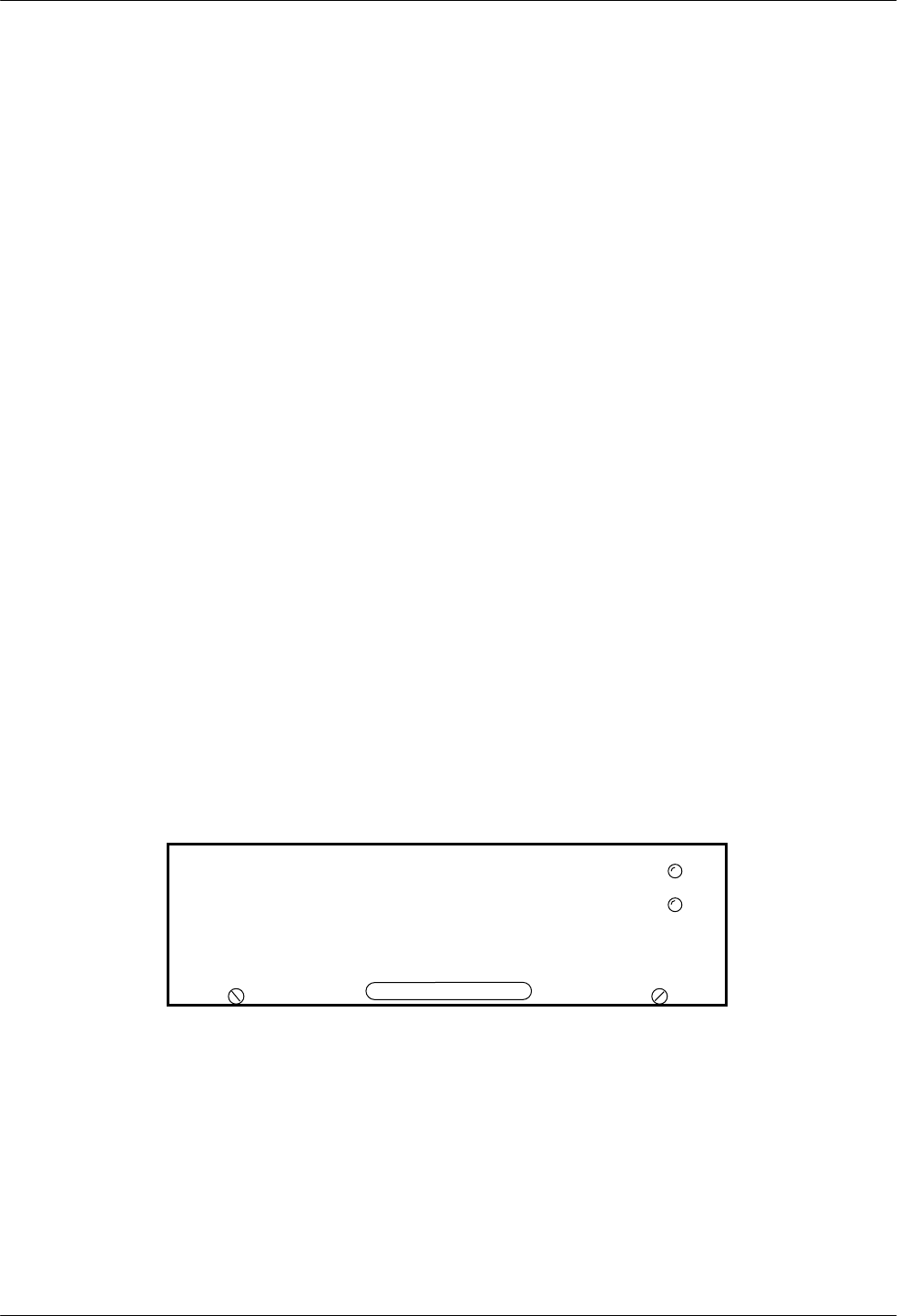
There are two LED status indicators (Figure 3-1) on
the power module’s faceplate: the Power LED and the Fan
Alarm LED. The Power LED provides the status of the
power module. A green light indicates that the power
module is operating properly. A red light indicates a
power module failure. No light indicates that the CO
Power Unit is not receiving input power. The Fan Alarm
LED provides the status of the fan in the power module. If
the Fan Alarm LED is not lit and the Power LED is green,
the fan is operating properly. If the LED is yellow, it
indicates either a fan failure or a fan speed below
1900 rpm.
3000 DC Power Module
Power
Fan Alarm
491-1369
8
Figure 3-1. LED Status Indicators
3