


Installation
2-93000-A2-GB41-40 May 1998
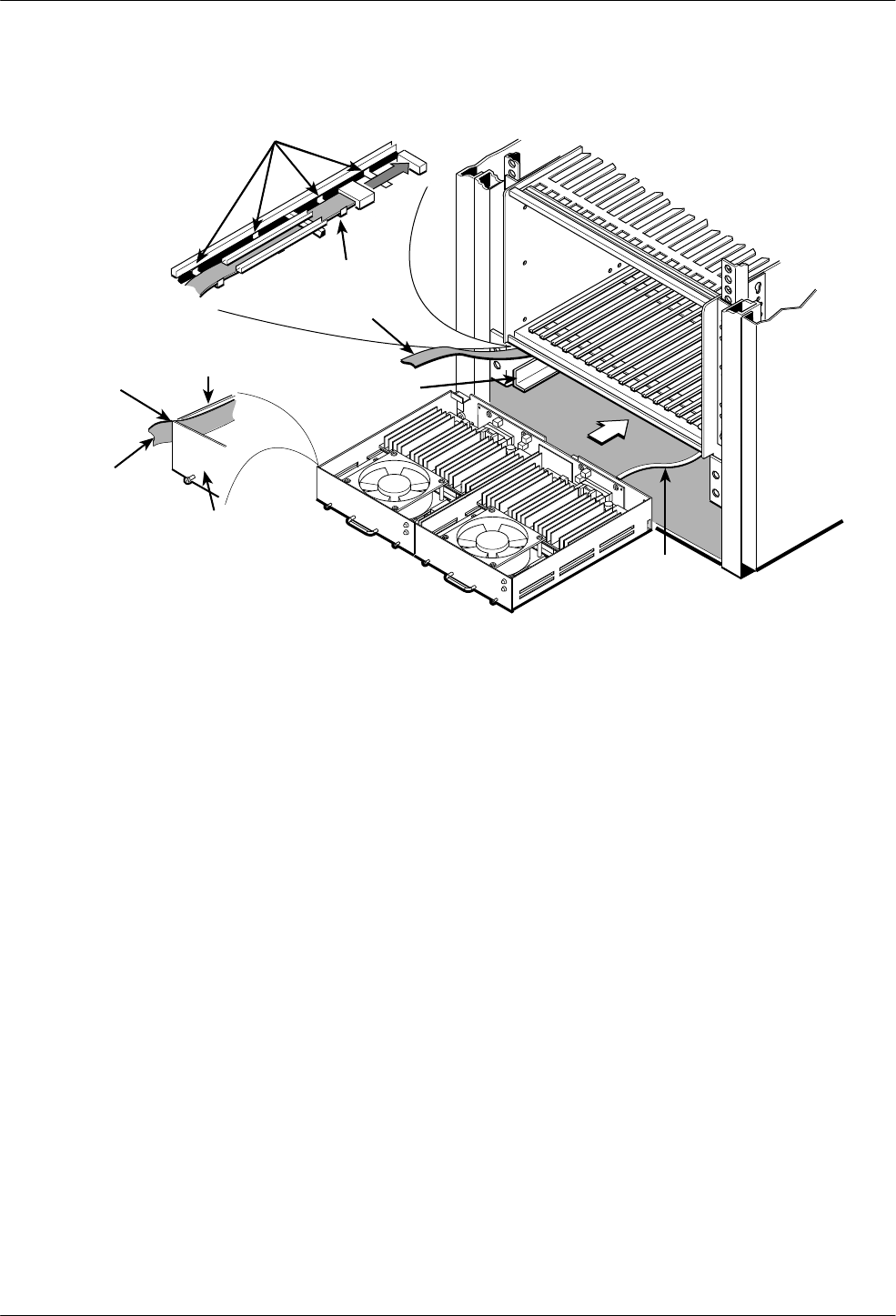
Built-in
Retainer
Clips
SDCP
Ribbon
Cabll
Space
Between
CO Power
Tray and
Power Module
SDCP
Ribbon
Cabll
Left
Power
Module
CO
Power
Tray
Flanges
Ground
Strap
496-13681-02
Power
Fan Alarm
3000 DC Power Module
Power
Fan Alarm
3000 DC Power Module
3000 DC Power Module
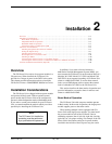
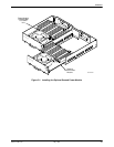
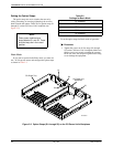
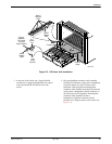
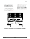
Figure 2-3. CO Power Unit Installation
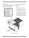
3. At the rear of the carrier, use a large flat-blade
screwdriver to engage and tighten the two captive
screws that fasten the CO Power Unit to the
carrier.
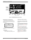
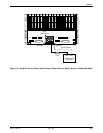
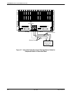
4. Plug one backplane connector cable assembly
from the P20 connector on the carrier’s backplane
to the P6 connector on the CO Power Unit’s
backplane. Then, plug the second backplane
connector cable assembly from the P19 connector
on the carrier’s backplane to the P3 connector on
the CO Power Unit’s backplane. The backplane
connector cable assemblies enable a
backplane-to-backplane connection which
provides low voltage dc power to the carrier (see
Figure 2-4).