


A-13000-A2-GB41–40 May 1998
Interface Connections
Overview A-1. . . . . . . . . . . . . . . . . . . . . . . . . . . . . . . . . . . . . . . . . . . . . . . . . . . . . . . . . . . . . . . . . . . . . . . . . .
DC Inputs A-1. . . . . . . . . . . . . . . . . . . . . . . . . . . . . . . . . . . . . . . . . . . . . . . . . . . . . . . . . . . . . . . . . . . . . . . . .
CO Alarm System Outputs A-4. . . . . . . . . . . . . . . . . . . . . . . . . . . . . . . . . . . . . . . . . . . . . . . . . . . . . . . . . . .
NMS Alarm Outputs A-5. . . . . . . . . . . . . . . . . . . . . . . . . . . . . . . . . . . . . . . . . . . . . . . . . . . . . . . . . . . . . . . . .
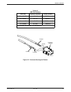
Overview
This appendix provides pin assignments for the dc
input connectors and alarm output connectors. It also
provides illustrations of the connectors on the rear of the
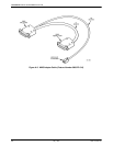
CO Power Unit and an NMS alarm adapter cable.
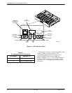
DC Inputs
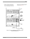
A pair of 2-pin AMP connectors on the CO Power
Unit’s backplane provides an interface between the dc
power input cable and the CO Power Unit (see
Figure A-1). Table A-1 lists the pin assignments for the dc
inputs.
A