


Interface Connections
A-53000-A2-GB41–40 May 1998
NMS Alarm Outputs
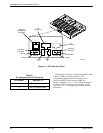
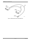
CO alarms can be sent to a Modular 3611 DSU (which
will then notify a 6800 Series NMS) via a 6-wire modular
jack on the CO Power Unit’s backplane (see Figure A-1).
(The Modular 3611 DSU must be configured to forward
alarms to a 6800 Series NMS.) Table A-4 lists the pin
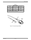
assignments for the NMS adapter cable. Figure A-3
illustrates the NMS adapter cable.
Note that a power failure alarm signal is sent to an
NMS upon a failure in either the –48V input or low
voltage output circuits, and that a fan failure alarm signal
is sent if the fan speed falls below 1900 rpm.
NOTE
To avoid potential problems
caused by incorrect connections
(e.g., grounding the +12 Vdc
source), do not set Jumper J21
as shown in Figure 2-10 of
Chapter 2 if you are not using
an NMS adapter cable.
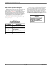
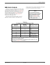
Table A-4
Pin Assignments for the NMS Adapter Cable
EIA 25-Pin
Male End
1
Modular
Plug End
NMS Alarm Function
1
2
6 +12 Vdc Source
11 4 None
14 3 None
16 5 None
19 2 Fan Status Alarm
23 1 Power Status Alarm
1
All other pins on the 25-pin male connector are wired straight through
to the 25-pin female connector.
2
This pin only functions as a +12 Vdc source when Jumper J21 is set
as shown in Figure 2-10 of Chapter 2.