


COMSPHERE –48 Vdc Central Office Power Unit
2-12 May 1998 3000-A2-GB41-40
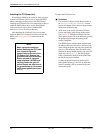
NOTE
The option straps must be set
for the Independent mode of
operation. For the correct
settings, see the
Setting the
Option Straps
section earlier in
this guide.
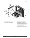
To provide power to the CO Power Unit operating in
Independent mode:
" Procedure
1. Use the two connector housings (AMP part
number 1-480698-0) and four crimp-type contacts
(AMP part number 350550-1) to attach the
connector(s) to your –48 Vdc power input
cable(s). Note that you need a hand crimping tool
(AMP part number 90296-2 or equivalent) to
build the connector(s).
(The contacts are crimp type and are intended for
use with 20 AWG through 14 AWG wire with a
maximum insulation diameter of .130 inches. For
additional information, see Appendix A of this
guide.)
2. Provide external fusing, if desired. (The fuses
shown in Figures 2-6 and 2-7 are optional as per
your requirements.) An optional external fuse
should have a rating of 6 amperes, 250 volts and
be a fast-acting type. Use a fuse similar to
Littlefuse #312006.
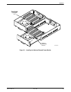
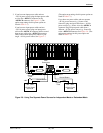
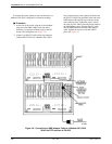
3. If you have two input power cables and two
separate –48 Vdc power sources (e.g., Source A
and Source B), plug one input power cable from
one of your –48 Vdc power sources (e.g.,
Source A) to the –48VDC A connector to provide
power to the left side of the carrier. Plug the other
input power cable from a different –48 Vdc power
source (e.g., Source B) to the –48VDC B
connector to provide power to the right side of the
carrier. See Figure 2-6. (The option strap settings
for this power option are listed in Table 2-3.)
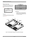
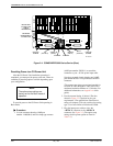
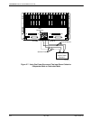
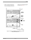
If you have two input power cables and one
–48 Vdc power source, plug one input power
cable into the –48VDC A connector and the
second input power cable into the –48VDC B
connector. Then, connect both power cables into
the same –48 Vdc power source. See Figure 2-7.
(The option strap settings for this power option are
listed in Table 2-3.)
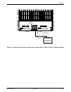
NOTE
The appropriate option strap
settings must be set. For the
correct settings, see the
Setting
the Option Straps
section earlier
in this guide.
To provide power to the CO Power Unit operating in
the Redundant mode:
" Procedure
1. Use the two connector housings (AMP part
number 1-480698-0) and four crimp-type contacts
(AMP part number 350550-1) to attach the
connector(s) to your –48 Vdc power input
cable(s). Note that you need a hand crimping tool
(AMP part number 90296-2 or equivalent) to
build the connector(s).
(The contacts are crimp type and are intended for
use with 20 AWG through 14 AWG wire with a
maximum insulation diameter of .130 inches. For
additional information, see Appendix A of this
guide.)
2. Provide external fusing, if desired. (The fuses
shown in Figures 2-5, 2-6, and 2-7 are optional as
per your requirements.) An optional fuse should
have a rating of 6 amperes, 250 volts and be a
fast-acting type. Use a fuse similar to Littlefuse
#312006.