


COMSPHERE –48 Vdc Central Office Power Unit
A-4 May 1998 3000-A2-GB41-40
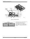
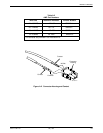
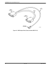
CO Alarm System Outputs
Both major (power) and minor (fan) alarms can be sent
to the CO alarm system via the Alarm A and Alarm B
output connectors. Figure A-1 illustrates these connectors.
The connector on the CO Power Unit’s backplane is an
AMP 5-position single row header. The mating connector
is an AMP MTE-type connector (part number 103957-4).
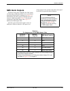
The CO alarm system outputs are relay contact
closures. Table A-3 lists the pin assignments for the CO
alarm system outputs.
Table A-3
Pin Assignments for the
CO Alarm System Outputs
Pin Number
Assigned To ...
1 Major Alarm (power failure)
2 Major Alarm (power failure)
3 No Connection
4 Minor Alarm (fan failure)
5 Minor Alarm (fan failure)
A contact closure is provided between Pin Numbers 1
and 2 to indicate a power failure. A contact closure is
provided between Pin Numbers 4 and 5 to indicate a fan
failure. Note that a major alarm signal is sent to a CO
alarm system upon a failure in either the –48V input or
low voltage output circuits, and that a minor alarm signal
is sent if the fan speed falls below 1900 rpm.
CAUTION
The relay contacts on the CO
Power Unit for the CO alarm
system have a rating of
0.1 amp maximum at 70 Vdc
maximum.