


Index
IN-2 July 2004 4821-A2-GN21-10
Ethernet
LEDs, 3-2
F
fasteners provided, 1-5
feature numbers, B-1
features, 1-1
feet, 1-12
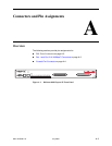
front panel, 3-1, A-1
illustration, A-1
LEDs, 3-1
G
glossary URL, iii
grounding screw, 2-7
H
hardware kit contents, 1-5
I
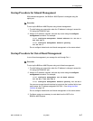
inband management
configuring, 4-5
described, 4-4
initialization procedures, 4-4
installation, 1-1
options, 1-2
installing
feet for shelf installation, 1-12
in rack, 1-8
mounting brackets for rack mount, 1-6
mounting brackets for wall mount, 1-10
on shelf or desktop, 1-12
screws for wall mount, 1-11
self-retaining nuts, 1-8
unit into rack, 1-8
unit on wall, 1-10
interfaces, C-1
J
jack screw, 2-2
L
LEDs, 3-1
License Agreement, B
Link LEDs, 3-2
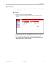
login, 4-4
lug for grounding, 2-7
M
management modes, 4-4
Management port
cabling, 2-4
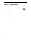
connector, A-3–A-4
description, 1-3
pin assignments, A-3–A-4
management port, 2-4
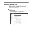
menu tabs, 4-6
models, 1-1
modem
connecting to Console port, 2-6
mounting brackets, description, 1-6
mounting configurations, 1-2, 1-6
N
network management systems, 4-8
NMS, 4-8
O
operating environment, C-1
optional mounting brackets, 1-6
order numbers, B-1
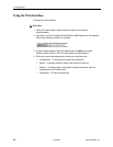
out-of-band management
configuring, 4-5
described, 4-4
overview
cabling, 2-1
configuration, 4-1
management modes, 4-4
of BitStorm 4800 Express, 1-1
of book, iii
P
package contents, 1-4
part numbers, B-1
password, 4-4
changing, 4-7
default, 4-4
PC cabling and settings, 2-5
physical dimensions, C-1
pin assignments, A-1
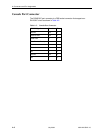
Console port, A-4
Management port, A-3–A-4
Ports 1 and 2, A-3
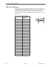
RJ21X connectors, A-2
Telco connectors, A-2
Port 1
cabling, 2-4
pinouts, A-3
Port 2
cabling, 2-3
pinouts, A-3