


T
M
T
M
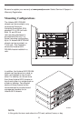
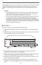
STACK
POSITION
2
3
6
5
4
1
AC
INPUT
1
2
3
E
S
D
E
S
D
48VDC CLASS 2
OR LIMITED
PW
R SOURCE
48V
A
R
TN
ABB
A
B
DC FUSES
T4A, M
IN. 48V
PW
R
A
ALM
FAN
B
O
U
T
IN SE
R
IA
L
A
LM
IN
T
F
M
C
P
/1
2
3
M
CP/
DSL
M
A
N
A
G
E
M
E
N
T
10 B
A
S
E
T
8610
99-16316
RTN–48V
AAB B
16
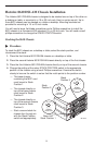
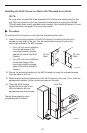
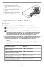
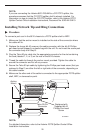
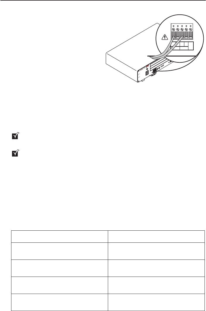
2. Dress the wires under the 8610
chassis to the left behind the support
foot.
3. Power the Hotwire 8610 DSLAM
chassis.
4. Make sure the PWR A LED on the
front panel is ON (green).
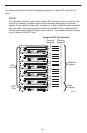
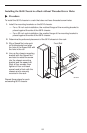
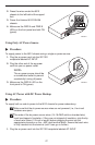
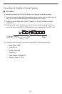
Using Two DC Power Sources for Power Redundancy
" Procedure
To supply two dc power sources to the 8610 chassis for power redundancy:
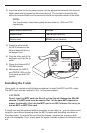
Make sure that the dc power source wires are not powered (i.e., the circuit
breakers are open).
The ends of the power source wires (14–18 AWG solid or stranded wire) must
be stripped of insulation to about 1/2-inch in length before plugging the wires
into the appropriate terminal on the –48V input terminal block. Ensure that
each wire is fully inserted into the terminal (until it can go no further).
1. Insert the following wires in the appropriate terminal and securely fasten each wire
by tightening the screw directly above it. The insulation should be fully within the
terminal block and no bare wire should be exposed outside of the block.
NOTE:
You should clearly label these power source wires as –48V and RTN
respectively.
Insert Power Source . . . Into the . . .
Negative side of the first power source
(Power Source A)
–48V A input terminal.
(Optional) Negative side of the second
power source (Power Source B)
–48V B input terminal.
Positive side of the first power source
(Power Source A)
RTN A (return) terminal.
(Optional) Positive side of the second
power source (Power Source B)
RTN B (return) terminal.