


20
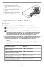
NOTE:
For detailed information about the configuration and operation of the circuit card,
see the appropriate card User’s Guide.
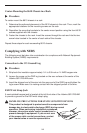
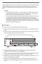
Verifying the Installation
To verify the hardware installation, observe the following indicators:
H The PWR A and/or PWR B LEDs on the front panel must be in the ON state
(green):
— If you are using a single –48 Vdc power source, then only the green
PWR A LED will be ON.
— If you are using dual Vdc power sources, then both the green PWR A and
PWR B LEDs will be ON.
— If you are using a single ac power source, then the green PWR A LED must
be ON.
— If you are using both an ac power source and a –48 Vdc power source, then
both the PWR A and PWR B LEDs must be ON.
H The yellow FAN ALM LED on the front panel must be OFF.
H Also check the SYSTEM LEDs on the MCP and DSL cards if you have not done so
already. The OK SYSTEM indicators on the cards must be in the ON state (winking
green).
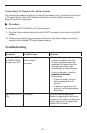
If these status indicators fail to appear as described, see
Troubleshooting
on page 25
and
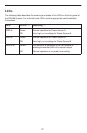
LEDs
on page 27 for more information.
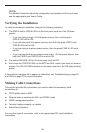
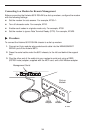
Making Cable Connections
This section provides the instructions you need to make the necessary cable
connections to:
H POTS splitter shelf or MDF
H Ethernet hubs or switches for MVL and RADSL cards
H SNMP management system
H Terminal, laptop computer, or modem
H Alarm Relay Interface
For any other type of connection, refer to the appropriate DSL card Installation
Instructions.