


26
97-15526
50
1
25
31
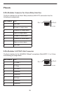
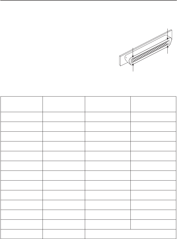
Telco 50-Pin Connector Pinouts for DSL Loops and POTS Splitters
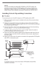
The three Telco 50-pin receptacles on the rear of the
chassis (labeled for Slots 1, 2, 3) provide the 2-wire loop
interface from each DSL port to either the POTS splitter
card or, if the loop is not being shared with POTS, then to
the Main Distribution Frame (MDF). The following table
lists the pin assignments for each of these interfaces.
NOTE:
When the 8610 chassis is the base chassis, the
MCP is installed in Slot 1 and the Tips and Rings
for Slot 1 are not connected internally and are not
active.
CONN #
for Slots 1–3
CONN PINS
(Tip, Ring)
CONN #
for Slots 1–3
CONN PINS
(Tip, Ring)
Port 1 1, 26 Port 14 14, 39
Port 2 2, 27 Port 15 15, 40
Port 3 3, 28 Port 16 16, 41
Port 4 4, 29 Port 17 17, 42
Port 5 5, 30 Port 18 18, 43
Port 6 6, 31 Port 19 19, 44
Port 7 7, 32 Port 20 20, 45
Port 8 8, 33 Port 21 21, 46
Port 8 9, 34 Port 22 22, 47
Port 10 10, 35 Port 23 23, 48
Port 11 11, 36 Port 24 24, 49
Port 12 12, 37 Port 25 25, 50
Port 13 13, 38