


Tools and Equipment for Installation and Maintenance 29
OnSite Series Getting Started Guide 3 • Installation Overview
Tools and Equipment for Installation and Maintenance
You need the following tools and equipment to install or upgrade the OS-10 system and its components:
• ESD-preventive cord and wrist strap (when working with modular components or expansion cards)
• Number 1 or number 2 Phillips screwdriver
• Mounting brackets (provided); two are required for rack mounting or for wall mounting
• 8 screws (provided) to secure the L mounting brackets to the OS-10 system chassis (four screws for each
bracket)
• A minimum of four 12-24 x 3/4-inch screws (not provided) to secure the OS-10 system chassis to the rack
• Suitable screws and wall anchors to install an OS-10 system on a wall
• Cable ties, if required, for organizing cables
In addition, depending on the type of modules you plan to use, you might need the following equipment to
connect the OS-10 system to an external network:
• Cables for connection to the fiber-optic and client signal ports (depending on configuration)
• Ethernet hub or PC with a network interface card for connection to Ethernet LAN ports
• Console terminal (an ASCII terminal or a PC running terminal emulation software) configured for 9,600
baud, 8 data bits, no parity, and 1 stop bit
OnSite System Installation
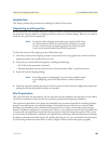
Note Read the information in this section thoroughly and completely
before you attempt to install or remove an OS-10 Series system chas-
sis.
Mounting the Chassis to an EIA/TIA 19-Inch Rack
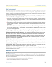
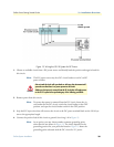
To install the OS-10 system chassis in an EIA/TIA 19-inch rack, see Figure 10 and follow these steps:
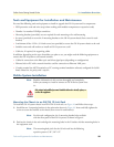
1. Install the two L mounting brackets in the orientation shown in Figure 10. Insert and fully tighten the
screws to secure the brackets to the chassis (four screws for each bracket).
Note For this rack configuration, the L mounting bracket holes are flush
with the front panel of the OS-10 system, as shown in Figure 4.
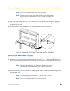
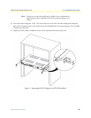
2. Position the chassis in the rack and align the mounting holes in the L bracket with the mounting holes in
the equipment rack.
Note The mounting-hole pitch for the 19-inch rack has the following
repetitive pattern: 5/8”- 5/8”-1/2”.
Only trained and qualified personnel should be allowed to install, replace, or
service this equipment.
WARNING