


OnSite System Installation 37
OnSite Series Getting Started Guide 3 • Installation Overview
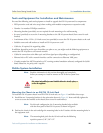
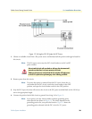
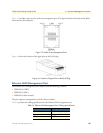
5. Connect the positive lead of the circuit to the return direction for “A” power on the OS-10 system termi-
nal block. See wiring 2-A in Figure 7.
Note The terminal block indicates the return direction for “A” power by
the letter R. This lead is second from the top on the OS-10 system
terminal block.
Note Step 4 and Step 5 results in the grounding of the return direction for
“A” power on the OS-10 system terminal block.
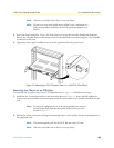
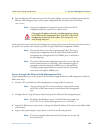
6. Connect the negative lead of the circuit to the “A” power input lead on the OS-10 system terminal block.
See wiring 3-A on figure 13 on page 36.
Note The terminal block indicates the “A” power lead by the letter A. This
lead is first from the top on the OS-10 system terminal block.
Continue with the following steps if a second circuit is available for the provision of redundant “A” and
“B” DC power inputs on the system. Otherwise, go directly to Step 10 to complete this task.
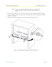
7. Connect the positive lead of this circuit to ground. See wiring 1-B on figure 13 on page 36.
Note As an option, you may choose another common grounding point
other than the oneshown in Figure 13. The choice depends on the
grounding practice for your particular location. Figure 13 shows the
grounding point colocated with the DC circuit for “B” power.
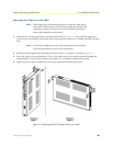
8. Connect the positive lead of the circuit to the return direction for “B” power on the OS-10 Series system
terminal block. See wiring 2-B on Figure 13.
Note The terminal block indicates the return direction for “B” power by
the letter R. This lead is fourth from the top on the OS-10 system
terminal block.
Note Step 7 and Step 8 result in the grounding of the return direction for
“B” power on the OS-10 system terminal block.
The ground wire should always be connected first and discon-
nected last.
The ground wire should always be connected first and discon-
nected last.
CAUTION
CAUTION