


OnSite System Installation 35
OnSite Series Getting Started Guide 3 • Installation Overview
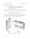
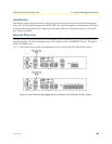
Powering On the OS-10 System with AC Power
To power on the OS-10 system using AC power, follow these steps:
1. Connect the AC power cable to the OS-10 system and then to the wall outlet.
2. Turn the power switch on the back panel of the OS-10 system to the ON position.
Note The green PWR (power) LED on the front panel is lit when the sys-
tem receives power from the AC source.
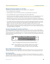
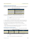
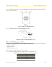
Connecting DC Power to the OS-10 System
If your OS-10 system has a DC-input power supply terminal block on the front panel, follow the directions in
this section for proper wiring.
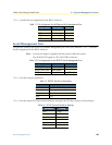
Table 9 summarizes the wiring requirements for the OS-10 system chassis with a DC-input power supply.
Note For installations compliant with the National Electric Code, an AWG
14 (2.0 mm2) wire is required for DC input and safety ground wire.
Note The input voltage tolerance limits for nominal –48 VDC power sup-
plies is –36 to –72 VDC.
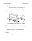
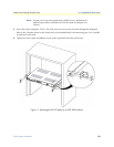
Wiring Procedure for DC Input Power
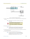
To connect DC power to the OS-10 system, see Figure 13 and follow these steps:
After turning off the AC power switch, wait for at least 3 seconds
before turning it back to the on position.
This product relies on the installation of the building for short-circuit (over-
current) protection. Ensure that the protective device is rated not greater than
15 A at 60 VDC.
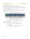
Table 9. DC Wiring Requirements for the OS-10 System Chassis
DC Nominal Input DC Input Wire Size
Safety Ground
Wire Size
Over-Current Protection
–48 VDC at 2.0 A
AWG 18 (1.0 mm
2
) AWG 14 (2.0 mm
2
)
15 A
•Connect the DC input wires to the OS-10 system with the following wiring
sequence.
•
Figure 13 shows the terminal block for the DC power supply on the OS-10
system. Wire the DC power supply as shown.
CAUTION
WARNING
WARNING