


13
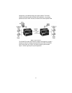
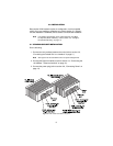
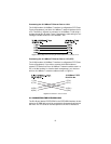
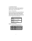
Connecting the 10/100Base-T Ethernet Port to a Hub
The VLINK modem 10/100Base-T interface is configured as DTE (Data
Terminal Equipment), just like a 10/100Base-T network interface card in
a PC. Therefore, it “expects” to connect to a 10/100Base-T Hub using a
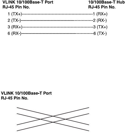
straight-through RJ-45 cable. Figure 7 diagrams the cable wiring for con-
necting the VLINK modem to a 10/100Base-T hub.
Figure 7.
Wiring diagram for connecting the VLINK modem to a 10/100Base-T hub
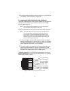
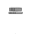
Connecting the 10/100Base-T Ethernet Port to a PC (DTE)
The VLINK modem 10/100Base-T interface is configured as DTE (Data
Terminal Equipment). If you wish to connect the VLINK modem to
another DTE devices such as 10/100Base-T network interface card in a
PC (or VLINK modems in a back-to-back arrangement), you must con-
struct a 10/100Base-T crossover cable as shown in Figure 8.
Figure 8.
10/100Base-T crossover cable
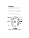
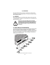
3.5 CONNECTING THE POTS/ISDN LINE
The RJ-45 port labeled “POTS/ISDN” is the POTS/ISDN interface. A tele-
phone or an ISDN device may be connected to this port and carried over
the VDSL line. The units do not need power for the POTS interface to
1 (TX+) 1 (TX+)
2 (TX-) 2 (TX-)
3 (RX+) 3 (RX+)
6 (RX-) 6 (RX-)
10/100Base-T DTE
RJ-45 Pin No.