


19
5.0 OPERATION
Once the VLINK modems are properly installed, they should operate
transparently. No user settings required. This section describes reading
the LED status monitors.
5.1 POWER UP
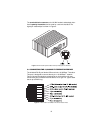
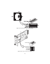
Before applying power to the VLINK modem, please review section 3.6,
“Connecting Power” on page 14 to verify that the unit is connected to the
appropriate power source.
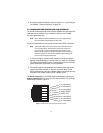
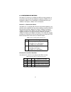
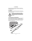
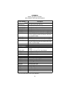
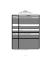
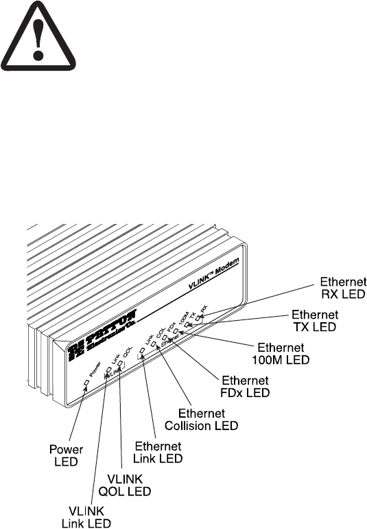
5.2 FRONT PANEL LED STATUS MONITORS
The VLINK modem features nine front panel LEDs (five on the rack card)
that monitor power, the Ethernet signals, and the VDSL connection.
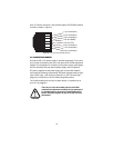
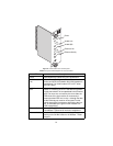
Figure 13 (standalone version) and Figure 14 on page 21 (rack card ver-
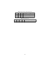
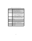
sion) show the front panel LEDs. Table 5 on page 20 describes the LED
functions for the standalone model, Table 6 on page 21 describes the
LED functions for the rack card.
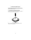
Figure 13.
VLINK modem standalone unit front panel
WARNING
There are no user-serviceable parts in the VLINK
modem.Fuse replacement should only be performed
by qualified service personnel. Contact Patton Elec-
tronics Technical support at (301) 975-1007 for more
information.