


2
CONTENTS
1.0 Warranty Information ................................................................. 4
1.1 Radio and TV Interference............................................................ 4
1.2 CE Notice...................................................................................... 4
1.3 FCC Part 68 (DV Version Only).................................................... 5
1.4 Industry Canada Notice ................................................................ 6
1.5 Service.......................................................................................... 6
2.0 General Information.................................................................... 7
2.1 Features........................................................................................ 7
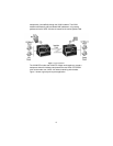
2.2 Description.................................................................................... 7
3.0 Installation................................................................................... 9
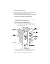
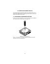
3.1 Standalone unit installation........................................................... 9
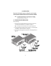
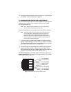
3.2 Rack card installation.................................................................. 10
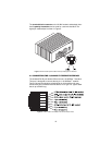
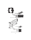
3.3 Connecting the Twisted-Pair Line Interface................................ 11
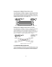
3.4 Connecting the 10/100Base-T Ethernet Interface ...................... 12
Connecting the 10/100Base-T Ethernet Port to a Hub............... 13
Connecting the 10/100Base-T Ethernet Port to a PC (DTE)...... 13
3.5 Connecting the POTS/ISDN line................................................. 13
3.6 Connecting Power ...................................................................... 14
4.0 Configuration (Model 1068 Only) ............................................ 15
4.1 Configuring the hardware DIP switches...................................... 15
4.2 Configuring DIP Switch S1 ......................................................... 17
Switch S1-1: Ethernet Auto Sense ............................................. 17
Switches S1-2 and S1-4: Data Rate........................................... 17
5.0 Operation................................................................................... 19
5.1 Power Up.................................................................................... 19
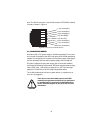
5.2 Front Panel LED Status Monitors ............................................... 19
A Specifications ........................................................................... 22
A.1 LAN Connection .......................................................................... 22
A.2 Transmission Line ....................................................................... 22
A.3 VDSL Line Rate ........................................................................... 22
A.4 VDSL Distance ............................................................................ 22
A.5 VDSL Surge Suppressor ............................................................. 22
A.6 LED Status Indicators ................................................................. 22
A.7 Power Supply .............................................................................. 22
A.8 Temperature Range .................................................................... 23
A.9 Humidity ...................................................................................... 23
A.10 Dimensions ................................................................................. 23
B Model 1058 Series Factory
Replacement Parts and Accessories...................................... 24
C MODEL 1068 series Factory
Replacement Parts and Accessories...................................... 25