


14
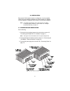
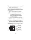
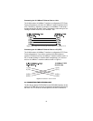
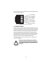
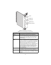
work. The RJ-45 connector in the VLINK modem’s POTS/ISDN interface
is wired as shown in Figure 9.
Figure 9.
VLINK (RJ-45) POTS/ISDN interface
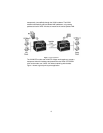
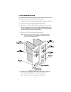
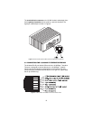
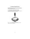
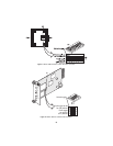
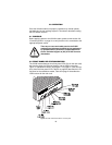
3.6 CONNECTING POWER
An external AC or DC power supply is available separately. This connec-
tion is made via the barrel jack on the rear panel of the VLINK standalone
modem. No configuration is necessary for the power supply (See Appen-
dix B for domestic and international power supply and cord options).
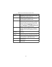
DC power (supplied via the power supply jack to the VLINK modem)
must meet the following requirements; DC power supplied must be regu-
lated +5VDC ±5%, 1.0A minimum. Center pin is +5V. The barrel type
plug has a 2.5/5.5/10mm I.D./O.D./Shaft Length dimensions.
The VLINK modem does not have a power switch, so it powers up as
soon as it is plugged in.
WARNING
There are no user-serviceable parts in the VLINK
modem.Fuse replacement should only be performed
by qualified service personnel. Contact Patton Elec-
tronics Technical support at (301) 975-1007 for more
information.
1 (no connection)
2 (no connection)
3 (no connection)
4 (2-wire RING)
5 (2-wire TIP)
6 (no connection)
7 (no connection)
8 (no connection)
1
2
3
4
5
6
7
8