


15
4.0 CONFIGURATION (MODEL 1068 ONLY)
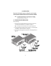
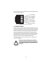
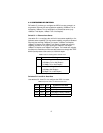
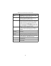
The VLINK modem has eight DIP switches for configuring the unit for a
wide variety of applications. This section describes switch locations and
explains the different configurations.
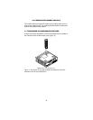
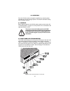
4.1 CONFIGURING THE HARDWARE DIP SWITCHES
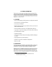
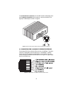
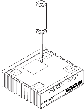
Using a small flat-tip screwdriver, remove the protective cover located on
the underside of the VLINK modem (see Figure 10).
Figure 10.
Removing protective cover
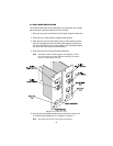
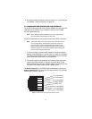
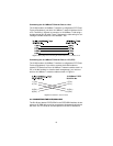
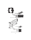
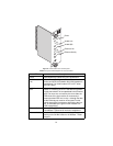
Figure 11 and Figure 12 on page 16 show the orientation of the DIP
switches in the On and Off positions.