


11
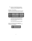
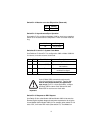
Switch S1-4: Must be set to the ON position (Reserved).
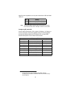
Switch S1-5: Asynchronous/Sync Operation
Use switch S1-5 to configure the Model 1082 for async/sync operation.
Switch S1-5 must be set in the Off position. There is no other valid set-
ting.
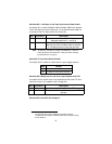
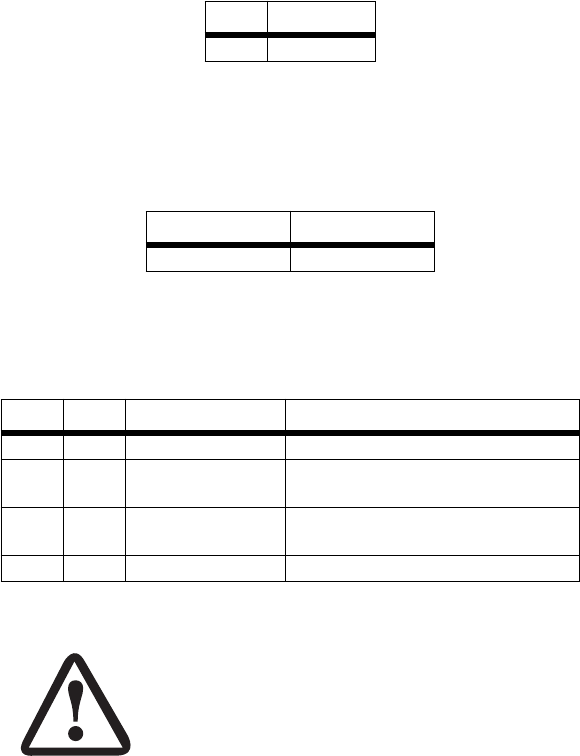
Switches S1-6 and S1-7: System Clock Mode
Use Switches S1-6 and S1-7 to configure the 1082 or Model 1082/144
for internal, or receive recover clock mode.
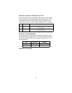
Switch S1-8: Response to RDL Request
Use Switch S1-8 to allow Model 1082 and Model 1082/144 to enter the
Remote Digital Loopback diagnostic test when requested to do so by the
far end Model 1082 or Model 1082/144. For example, when switch S1-8 is
set to “ON”, it will enter RDL mode (See section 5.3, “Test Modes” on
S1-4 Setting
On Reserved
S1-5 Setting
Off Async/Sync
S1-6 S1-7 Clock Mode Description
On On Internal System clock generated internally
Off On External (DTE) System clock derived from termi-
nal interface
On Off Receive Recover System clock derived from the
received line signal
Off Off Hardware Reset
Important
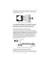
A pair of Model 1082s communicate synchronously
across the twisted pair line connection. Therefore,
you
must set these switches whether your application is
async or sync
. For X.21 or Async applications, configure
one Model 1082 for internal clock mode and the other
Model 1082 for receive recover clock mode.