


2
TABLE OF CONTENTS
1.0 Warranty Information ................................................................. 4
1.1 FCC Information ........................................................................... 4
1.2 CE Notice...................................................................................... 4
1.3 Service.......................................................................................... 5
2.0 General Information.................................................................... 6
2.1 Features........................................................................................ 6
2.2 Description.................................................................................... 6
2.3 1082 SNMP Management Solutions............................................. 7
HTTP/HTML Management ........................................................... 7
3.0 Configuration .............................................................................. 8
3.1 Configuring the Hardware DIP Switches ...................................... 8
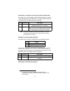
Configuring DIP Switch S1 ........................................................... 9
Switches S1-1 and S1-2: Data Rate........................................... 10
Switch S1-3: Data Set Ready during Line Loopback Test.......... 10
Switch S1-4: Must be set to the ON position (Reserved). .......... 11
Switch S1-5: Asynchronous/Sync Operation.............................. 11
Switches S1-6 and S1-7: System Clock Mode........................... 11
Switch S1-8: Response to RDL Request.................................... 11
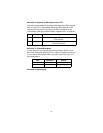
Configuring DIP switch S2.......................................................... 12
Switches S2-1: 19.2 kbps or 144 kbps Synchronous
Rate Enable................................................................................ 13
Switch S2-2: Front Panel Switch Disable ................................... 13
Switches S2-3: Response to Local Line Loop
Requests from DTE.................................................................... 13
Switches S2-4 and S2-5: Not Assigned...................................... 13
Switch S2-6: Response to RDL Request from DTE ................... 14
Switch S2-7: Compatability Mode............................................... 14
Switch S2-8: Not Assigned......................................................... 14
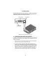
4.0 Installation................................................................................. 15
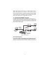
4.1 Connecting the Twisted Pair Interface........................................ 15
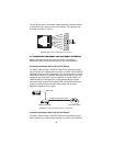
4.2 Connecting the Model 1082 (V.35) Serial Interface.................... 16
Connecting the Model 1082 (V.35) to a DTE Device.................. 16
Connecting the Model 1082 (V.35) to a DCE Device ................. 16
4.3 Connecting the Model 1082 (X.21) Serial Interface.................... 17
Connecting the Model 1082 (X.21) to a “DCE” or
“DTE” Device.............................................................................. 17
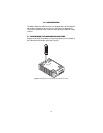
Opening the Case....................................................................... 18
4.4 Connecting Power ...................................................................... 19
Universal AC Power (100–240VAC)........................................... 19
DC Power ................................................................................... 20
5.0 Operation................................................................................... 21
5.1 Power-up .................................................................................... 21
5.2 LED Status Monitors................................................................... 21
5.3 Test Modes................................................................................. 22