


19
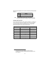
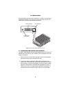
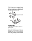
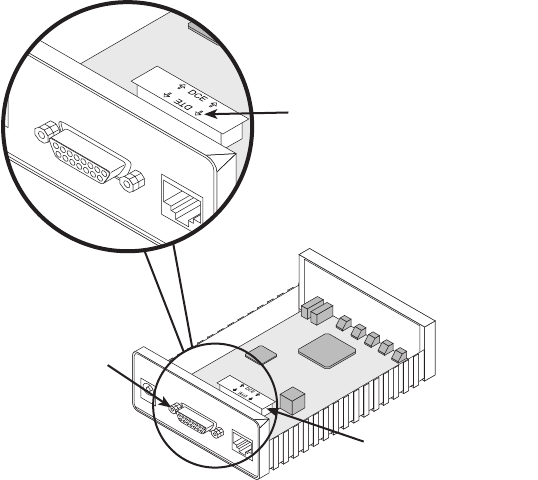
The DCE/DTE strap is located on the top side of the 1082 PC board (see
Figure 10). The arrows on the top of the strap indicate the configuration
of the X.21 port (for example, if the DTE arrows are pointing toward the
DB-15 connector, the X.21 port is wired as a DTE). Change the DCE/
DTE orientation by pulling the strap out of its socket, rotating it 180º, then
plugging the strap back into the socket. To close the case, fit the two
halves together snugly and snap them back in place.
Figure 10.
Setting the DCE/DTE strap
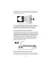
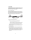
4.4 CONNECTING POWER
The Model 1082 (all versions) are available with Universal AC (100–
240VAC), 120VAC, 230VAC or -48VDC power options. This section
describes these options.
Universal AC Power (100–240VAC)
The Model 1082 uses a 5VDC, 2A universal input 100-240VAC, power
supply (center pin is +5V). The universal input power supply has a male
IEC-320 power entry connector. This power supply connects to the
Model 1082 by means of a barrel jack on the rear panel. Many interna-
tional power cords are available for the universal power supply (Refer to
Appendix B, “Model 1082C and 1082D Factory Replacement Parts and
Accessories” on page 27 for country-specific power cords.
G.703/G.704 Test Modes
511E
Model 1194E Single Mode Fiber - Quad G.703/G.704 Modem
Line
Power
Made in the USA
Interface
In this example, the DCE/DTE
strap is configured for DTE
because the DTE label on the
strap is pointed toward the
DB-15 connector
G.703/G.704 Test Modes
511E
l 1194E Single Mode Fiber - Quad G.703/G.704 Modem
Line
er
Made in the USA
Interface
DCE/DTE
strap
DB-15 (X.21)
connector