


9
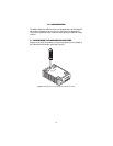
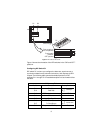
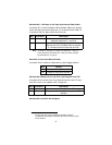
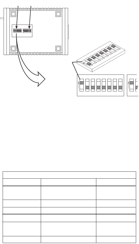
Figure 3.
DIP switches S2 and S2
Figure 3 shows the orientation of the DIP switches in the “ON” and “OFF”
positions.
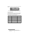
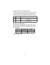
Configuring DIP Switch S1
DIP switch S1 is where you configure the data rate, asynchronous or
synchronous data format, transmit clock source, and response to RDL
request. The following table summarizes default positions of DIP
switches S1-1 through S1-8. Detailed descriptions of each switch follow
the table.
S1
S2
1234
ON
5678
1234
ON
5678
1234
ON
5678
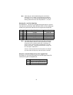
Push toggle up
for ON position
Switch toggle
Push toggle
down for
OFF position
1234
ON
5678
S1
S1
12
ON
S1 S2
Position Function Factory Default
S1-1 Data Rate On
S1-2 Data Rate Off
On DSR On
S1-4 Reserved On
S1-5 Async/Sync Data Format Off
S1-6 Tx Clock Source On
S1-7 Tx Clock Source On
S1-8 Response to RDL Request On Enable
64K Sync
}
}
Internal Clock
S1 Summary Table
DSR during Local Line LoopS1-3