


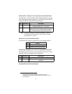
17
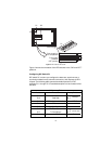
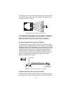
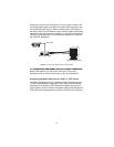
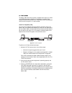
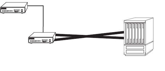
designed to connect to DTE equipment, such as a router. However, tail-
circuit applications require connection to another DCE equipment, such
as a multiplexer (see Figure 7). When connecting the V.35 interface of
the Model 1082 to your DCE device, use a V.35 null modem cable. Some
applications may also require the installation of a V.35 tail-circuit buffer to
account for small differences in clock frequency between the 1082 and
the V.35 DCE (Multiplexer).
Figure 7.
Connecting the Model 1082 to V.35 serial DCE
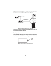
4.3 CONNECTING THE MODEL 1082 (X.21) SERIAL INTERFACE
Model 1082 supports X.21 serial port connections. This section
describes how to connect the serial ports to your X.21 equipment.
Connecting the Model 1082 (X.21) to a “DCE” or “DTE” Device
The Model 1082 provides an X.21 interface on a DB-15 female connector.
The X.21 interface default configuration is DCE (Data Circuit Terminating
Equipment) for connection to DTE (Data Terminal Equipment) such as a
router. However, the X.21 interface on the Model 1082 may be configured as
DTE (Data Terminal Equipment) for connection to DCE such as a modem or
V.35 Multiplexer (DCE)
Model 1082 (DCE)
Model 1082
DSL Span