


24
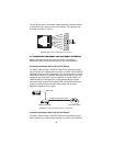
Using the V.52 (BER) test pattern generator
To use the V.52 BER tests in conjunction with the Remote Digital Loop-
back tests (or with Local Line Loopback tests), do the following:
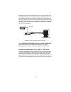
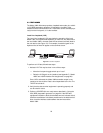
1. Locate the
511/511E
toggle switch on the front panel of the
Model 1082 and set the toggle to the down position. This activates
the V.52 BER test mode and transmits a
511
test pattern into the
loop. If any errors are present, the local modem’s red
ER
LED will
blink continuously.
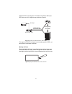
2. If the above test indicates that no errors are present, move the V.52
toggle switch to the up position, activating the 511/E test with errors
present. If the test is working properly, the local modem’s red
ER
LED will blink. A successful 511/E test will confirm that the link is in
place, and that the Model 1082’s built-in 511 generator and detector
are working properly.