Model 3125 installation 27
Model 3125 RAS Getting Started Guide 2 • Hardware installation
Model 3125 installation
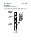
Installing the 3125TM Transition Module
1. If necessary, refer to the instructions in your chassis user manual to remove any outer covers so you can
access the cPCI rack card cages.
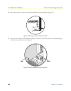
2. If there is not a slot filler panel installed, go to step 3. Otherwise, remove the two screws (located at the top
of the filler panel and at the bottom) that secure the panel to the card cage.
3. Remove the 3125TM Transition Module from its anti-static bag.
Note Be sure to wear the anti-static strap to prevent electrostatic damage to
the module.
Note The module should be installed as close as possible to the termination
jack provided by the Telco. The location should be well ventilated.
Do not block the chassis rack cooling vents.
The resource and transition modules can easily be damaged by
electrostatic discharge (ESD) resulting from the build-up of electri-
cal potential on clothing and other materials.
To avid damaging the 3125 modules, perform the following
safety and ESD preventive measures:
• Attach a ground strap to your wrist when connecting, discon-
necting, or handling the modles. Connect the other end of the
strap to a grounded surface.
• Keep the module in anti-static bags until they are needed.
• Remove a board from its anti-static bag only after you are cor-
rectly grounded by a ground strap.
• Place the modules only on an anti-static mat. Do not place
boards on top of an anti-static bag unless the outside of the
bag also provides anti-static protection.
Verify that the chassis rack is properly grounded before installing
the Model3125. An adequate ground can be achieved by con-
necting a #10 AWG ground wire between the chassis rack
ground stud and one of the following ground sources:
• The building ground rod (generally located at the site’s main
service entrance)
• A sprinkler pipe
• A cold water pipe
• Building structural steel


