


11
4.1 CONFIGURING THE DIP SWITCHES
The Model 3088 is equipped with two sets of DIP switches, which allow con-
figuration of the unit for a wide variety of applications. This section describes
switch locations and explains all possible configurations.
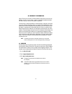
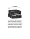
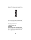
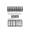
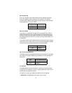
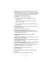
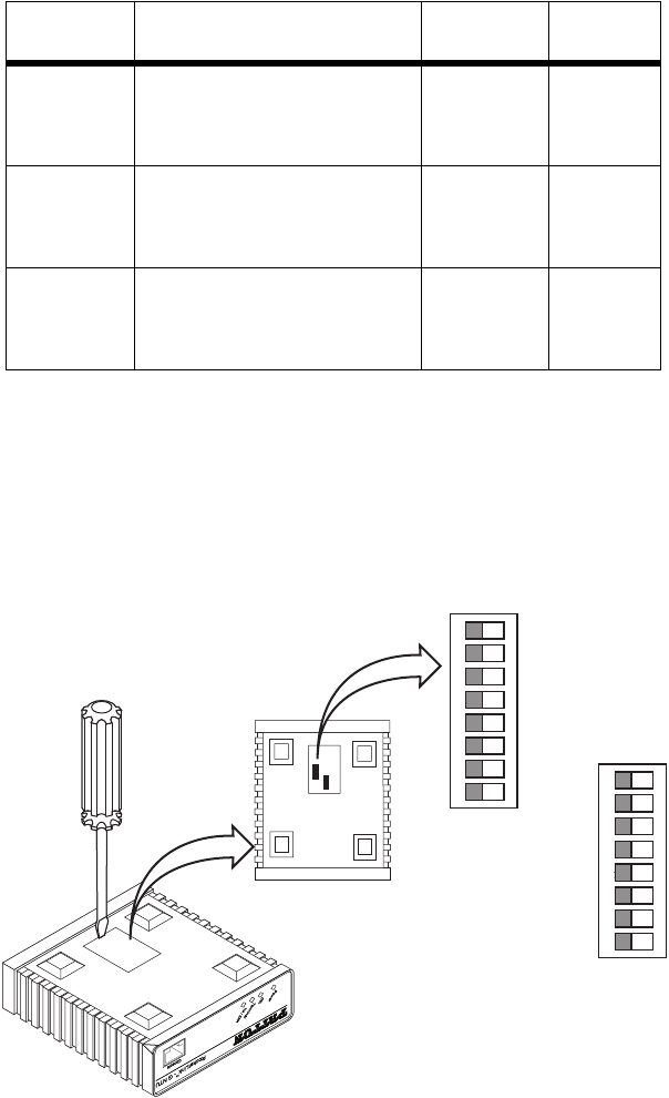
The two sets of DIP switches are externally accessible from the under-
side of the Model 3088 (see figure 2).
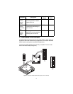
Figure 2.
Underside of Model 3088 showing location of DIP switches
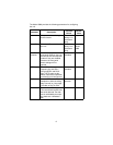
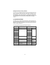
DSL Error
Monitor
Interval
Count
The number of errored inter-
vals allowed before restart-
ing the DSL link.
1–255 3
DSL Error
Monitor
Total Inter-
vals
The number of intervals to
inspect before disabling the
error monitor.
0–255 10
DSL Error
Monitor
Startup
Delay
The length, in seconds, to wait
after DSL link comes up before
enabling the error monitor.
0–255 5
Parameter Description
Possible
Values
Default
Value
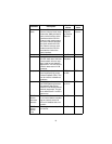
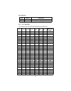
G.703/G.704 Test Modes
Model 1194E Single Mode Fiber - Quad G.703/G.704 Modem
123 4567 8
ON
123 4567 8
ON
S1
S2
1 2 3 4 5 6 7 8
ON
1 2 3 4 5 6 7 8
ON
S1
S2