


34
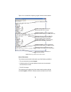
Term (Green)
The Term LED glows solid under the following circumstances:
• 3088/CA with V.35 interface: If the serial interface has asserted DTR
• 3088/D with the X.21 interface:
– Configured as DCE: Indicates that the “Control” signals have
been asserted.
– Configured as DTE: Indicates that the “Indication” signals have
been asserted
TM/ER (Red)
The TM/ER LED is used to indicate that a test mode is in progress or an
error has been detected. It blinks once every second while a test mode is
starting. It glows solid while a test mode is in progress. It blinks once if an
error is detected either during a test mode, or in normal DSL operation.
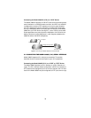
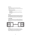
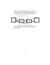
6.3 TEST MODES
The 3088 offers test modes in the form of loopbacks, PRBS pattern gen-
erators, and combinations of both. This section discusses how the test
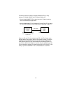
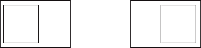
modes work. Figure 12 is a block digram of the Model 3088 with respect
to test modes.
Figure 12. Model 3088 Block Diagram
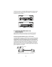
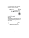
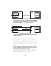
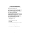
Loopbacks
The 3088 supports both Local Analog Loopbacks (LAL) and Remote
Digital Loopbacks (RDL). These can be initiated either from the optional
front panel switches or by the console command dsl set loopback
<off|lal|rdl>. The data path for the LAL is shown in figure 13.
DSL
Framer
511 Pattern
Generator
511 BER
Meter
DSL
Framer
511 Pattern
Generator
511 BER
Meter
Line